
Drivers often notice immediate signs of a failing Transmission Solenoid Valve. These include erratic shifting, delayed gear engagement, or transmission slipping. Such issues arise from the solenoid’s inability to precisely regulate hydraulic fluid pressure. This directly impacts transmission performance, leading to unreliable and inefficient operation.
Key Takeaways
- Transmission solenoid valves control gear shifts. They use fluid pressure. Problems cause bad shifting or delays.
- Look for signs of trouble. These include rough shifts, slow gear changes, or the ‘check engine’ light. These signs mean a solenoid might be bad.
- Use special tools to find problems. An OBD-II scanner reads codes. A multimeter checks electrical parts. These help fix issues quickly.
Understanding Transmission Solenoid Valve Fundamentals
What are Transmission Solenoid Valves
Transmission Solenoid Valves are crucial electro-hydraulic components in automatic transmissions. They function as two-position control devices, regulating the flow of Automatic Transmission Fluid (ATF) to various spool-type control valves. A solenoid valve fundamentally consists of several key parts: a solenoid coil, which generates a magnetic force when energized; a spool, which moves to control fluid channels; a valve body, housing the spool and fluid pathways; a spring, returning the spool to its original position; and seals, preventing fluid leakage. When the solenoid coil receives electrical current, it creates a magnetic field. This field attracts the spool, overcoming the spring’s force and moving the spool to open or close a fluid channel. When power is removed, the magnetic field disappears, and the spring pushes the spool back, altering the fluid path.
Types of Transmission Solenoid Valves
Automatic transmissions utilize various types of solenoid valves, each designed for specific control functions. Common types include variable force solenoids, on-off solenoids, pulse-width modulated solenoids, and low leak variable bleed solenoids. Based on their internal structure, these can be broadly categorized into switch-type (on-off) solenoid valves and pulse-type solenoid valves. Switch-type solenoids operate with a simple on/off action, directly connecting to a power source. Pulse-type solenoids, however, require careful handling during voltage detection due to their low resistance, often needing a series resistor to prevent coil damage.
How Solenoid Valves Control Gear Shifts
Transmission Solenoid Valves precisely control gear shifts by regulating the flow of transmission fluid. This fluid generates the hydraulic pressure essential for engaging and shifting gears. The vehicle’s Transmission Control Module (TCM) or Engine Control Unit (ECU) sends electrical signals to the solenoids. These signals instruct the solenoids when and how to move fluid, thereby controlling gear engagement and achieving the desired gear ratio. Key components like the valve body, inlet and outlet ports, the solenoid coil, a plunger, and a spring work in concert. The plunger, a movable metal core, responds to the magnetic field generated by the coil, opening or closing the fluid pathway. This precise interaction ensures seamless gear transitions, adapting to real-time driving conditions based on factors such as vehicle speed and throttle input.
Recognizing Symptoms of Faulty Transmission Solenoid Valves
Identifying the early signs of a failing transmission component can prevent more extensive damage. Faulty Transmission Solenoid Valves often manifest through distinct symptoms. Recognizing these indicators helps technicians diagnose issues accurately and promptly.
Identifying Erratic Shifting Patterns
Drivers often experience noticeable changes in how their vehicle shifts gears when a solenoid valve malfunctions. These changes include rough or delayed shifting, which feels like the transmission hesitates before engaging the next gear. Erratic or harsh shifting also occurs, characterized by abrupt shifts or noticeable jolts during gear changes. Sometimes, a vehicle exhibits a significant delay in shifting, a lag between the driver initiating a gear change and its actual occurrence. The transmission might also slip out of gear unexpectedly or fail to engage a specific gear altogether. These inconsistent shifting behaviors point directly to problems within the transmission’s control system.
Diagnosing Delayed Gear Engagement
Delayed gear engagement is another common symptom indicating issues with transmission solenoids. When a driver selects a gear, the transmission takes an unusually long time to respond. Failing shift solenoids, which are electronically controlled valves directing fluid for gear engagement, often cause this delay. If these solenoids fail or become stuck, they cannot properly direct the transmission fluid. Faulty shift solenoids are a common cause of delayed gear engagement. Over time, constant heat and vibration can cause their tiny plungers or electromagnetic coils to fail. When these coils fail, the solenoid cannot open or close correctly, preventing it from assisting in engaging the subsequent gear. This leads to a noticeable lag before the transmission fully engages the desired gear.
Understanding Limp Mode Activation
A vehicle entering “limp mode” often signals a serious transmission problem, potentially involving a Transmission Solenoid Valve. Limp mode activation is directly linked to transmission solenoid valve malfunctions. This mode acts as a safety mechanism, designed to limit performance and prevent further damage to the transmission and engine when the car’s computer detects a serious error. When activated, limp mode typically restricts engine RPMs and forces the car into one or two lower gears. This significantly reduces vehicle speed and overall performance, allowing the driver to reach a service center without causing catastrophic damage. A solenoid malfunction could be the underlying cause for the vehicle staying in a lower gear to protect the transmission.
Interpreting Check Engine Light Codes
The illumination of the Check Engine Light (CEL) on the dashboard is a general indicator of a problem, but specific diagnostic trouble codes (DTCs) often point directly to transmission solenoid issues. When the vehicle’s onboard diagnostic system detects an anomaly in the transmission’s operation, it stores a code and triggers the CEL. Technicians use an OBD-II scanner to retrieve these codes. Codes such as P0750, P0755, P0760, P0765, or P0770 typically indicate a malfunction in a specific shift solenoid or its circuit. These codes provide valuable clues, guiding the diagnostic process toward the affected solenoid valve.
Detecting Transmission Slippage
Transmission slippage presents as a distinct sensation where the engine revs without a corresponding increase in vehicle speed, or even causes deceleration. When a transmission slips due to a faulty solenoid valve, it behaves as if it is shifting into neutral, disengaging from the selected gear. This occurs because a loss of transmission fluid pressure prevents the transmission from maintaining the gear it is supposed to be in. The engine might sound like it is working harder, but the power does not effectively transfer to the wheels. This symptom indicates the transmission struggles to hold gears, often due to a solenoid’s inability to regulate fluid pressure correctly.
Essential Tools for Professional Transmission Solenoid Valve Diagnosis
Accurate diagnosis of transmission issues requires specialized tools. Professionals rely on specific equipment to pinpoint problems effectively. These tools help identify the root cause of transmission malfunctions.
Utilizing an OBD-II Scanner
An OBD-II scanner is a fundamental diagnostic tool. Technicians use it to read error codes triggered by a malfunctioning transmission solenoid. This device helps determine if a trouble code specifically points to a transmission solenoid issue or another problem. Diagnosing a faulty solenoid often necessitates an OBD-II scanner to access transmission-related trouble codes. It provides crucial initial information for the diagnostic process.
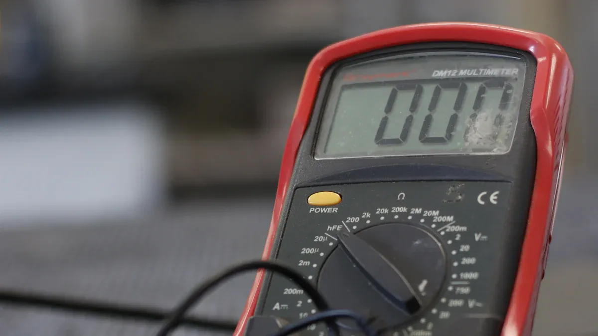
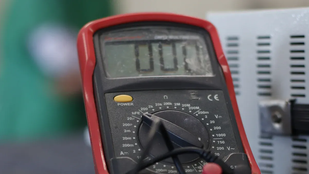
Employing a Multimeter for Electrical Checks
A multimeter performs essential electrical checks on solenoids. For resistance testing, set the multimeter to measure resistance (Ω). Connect the probes to the solenoid’s two testable terminals. Consult the manufacturer’s manual if unsure about terminal locations. Note the reading and compare it to the manufacturer’s specified range. An ‘OL’ reading indicates an open circuit, suggesting a faulty coil or wire. This requires replacement. For voltage testing, determine if the solenoid uses AC or DC voltage from its manual. Set the multimeter to the appropriate AC (V~) or DC (V…) voltage setting. Connect the probes to the solenoid terminals. If the solenoid functions correctly, the multimeter should display a voltage matching the valve’s rated voltage. A discrepancy indicates a faulty coil.
Using a Transmission Pressure Gauge
A transmission pressure gauge measures hydraulic fluid pressure within the transmission. Solenoids control this pressure. Incorrect pressure readings can indicate a faulty solenoid. This tool helps confirm if a solenoid properly regulates fluid flow. It provides direct evidence of hydraulic system performance.
Consulting Vehicle-Specific Service Manuals
Vehicle-specific service manuals are indispensable resources. They provide detailed specifications, wiring diagrams, and diagnostic procedures. These manuals offer correct resistance values for solenoids and proper testing sequences. Technicians rely on them for accurate troubleshooting and repair information.
Step-by-Step Transmission Solenoid Valve Testing Procedures

Diagnosing a faulty transmission solenoid valve requires a systematic approach. Professionals follow a series of precise steps to accurately identify the root cause of transmission issues. These procedures combine electronic diagnostics with physical inspections and hydraulic tests.
Retrieving and Analyzing Diagnostic Trouble Codes
The diagnostic process begins with retrieving Diagnostic Trouble Codes (DTCs) from the vehicle’s onboard computer. Technicians use an OBD-II scanner to connect to the vehicle’s diagnostic port. This tool reads codes stored by the Transmission Control Module (TCM) or Engine Control Unit (ECU). Specific codes often point directly to solenoid malfunctions. For example, a P0750 code specifically indicates a malfunction in Shift Solenoid A. This solenoid controls transmission fluid flow and gear selection. A P0750 code can lead to issues like delayed or harsh shifting, poor fuel efficiency, and potential transmission failure. Other codes, such as P0750-P0770, also indicate solenoid failure. These codes prevent proper transmission fluid flow and gear shifting, with the specific code depending on the affected gear in automatic transmissions. Analyzing these codes provides crucial initial guidance for further investigation.
Performing a Thorough Visual Inspection
After retrieving DTCs, a comprehensive visual inspection is essential. Technicians look for any obvious signs of damage or wear. This includes checking the transmission housing for fluid leaks, which can indicate seal failures or cracks. They also inspect the wiring harness connected to the solenoids for frayed wires, corrosion, or loose connections. Connectors themselves require scrutiny for bent or pushed-out pins, moisture intrusion, or signs of overheating. Sometimes, external damage to the transmission pan or valve body can suggest internal issues affecting solenoid operation. A clean and intact electrical connection is vital for proper solenoid function.
Conducting Electrical Resistance and Continuity Tests
Electrical tests confirm the integrity of the solenoid’s internal coil and its associated wiring. Technicians use a multimeter for these checks.
- Disconnect the Solenoid: Unplug the electrical connector from the solenoid. This may require removing the transmission pan or accessing an external connector.
- Set the Multimeter: Configure the digital multimeter (DMM) to the Ohms (Ω) setting.
- Consult the Service Manual: Refer to the manufacturer’s specified resistance range for the exact solenoid model being tested. This step is crucial for accurate comparison.
- Probe the Pins: Touch the multimeter’s two probes to the two electrical pins on the solenoid.
- Read the Value: Compare the multimeter’s reading to the specified range. A reading within specification indicates the solenoid’s coil is electrically sound. An ‘OL’ (Over Limit) or infinite resistance signifies an open circuit, meaning the coil wire is broken. This requires solenoid replacement. Zero or very low resistance points to a short circuit, where coil windings have melted together. This also necessitates solenoid replacement. A shorted solenoid can damage the TCM’s driver circuit.
For wiring harnesses, continuity tests are performed:
- Continuity Check: Disconnect the harness from both the solenoid and the TCM. Set the multimeter to the continuity setting. Touch one probe to a wire’s pin at the solenoid end and the other to the corresponding pin at the TCM end. A beep indicates a complete circuit; no beep signifies an open circuit.
- Short-to-Ground Check: With the harness disconnected at both ends, touch one multimeter probe to a wire’s pin and the other to a clean metal ground on the vehicle’s chassis or transmission case. The multimeter should display “OL” (no continuity). A beep indicates the wire is shorted to ground.
- Short-to-Other-Wire Check: Check for continuity between one wire and all other wires in the harness. There should be no continuity between any of them. A beep indicates that two wires have damaged insulation and are touching.
- Connector Inspection: Visually inspect connectors for bent or pushed-out pins, corrosion, or moisture intrusion, as these can cause poor connections.
Monitoring Solenoid Valve Operation with Live Data
Live data monitoring provides real-time insights into solenoid behavior. While scan tools typically display the ‘commanded status’ of a solenoid (whether it is instructed to be on or off), this does not always reflect its actual electrical activation or mechanical movement. Data transmission from the vehicle to the scan tool involves delays, making it difficult to diagnose electronic systems that fail in milliseconds.
More advanced methods offer greater accuracy:
- Oscilloscope Monitoring: This method directly monitors the current and voltage of solenoid windings. It provides real-time and accurate data, unlike scan tools which have delays and show commanded status.
- Outcome Method: This infers solenoid operation by monitoring gear ratio changes using engine RPM and vehicle speed sensors. If a commanded gear shift results in the expected ratio change, the solenoid is assumed to have functioned.
- TCM Hardware Monitoring: Some Transmission Control Modules (TCMs) incorporate shunts to directly monitor solenoid current, though this adds to manufacturing cost.
- Pressure Switches: Some TCMs use pressure switches to check solenoid commands. If a pressure switch activates at the wrong time, the transmission defaults.
- Key-on Solenoid Circuit Test: The TCM runs a diagnostic test when the ignition is first turned on. This test cycles each solenoid to check its circuit. An oscilloscope can monitor this test.
Executing Hydraulic Pressure Tests
Hydraulic pressure tests directly assess the solenoid’s ability to regulate fluid pressure within the transmission. This provides definitive proof of a solenoid’s mechanical function.
For on/off solenoids, the procedure involves:
- Apply pressure to the inlet.
- If normally closed, ensure no pressure is at the outlet; if normally open, ensure pressure is at the outlet.
- Energize the solenoid.
- If normally closed, ensure pressure is at the outlet; if normally open, ensure no pressure is at the outlet.
- Crucially, check for any leakage through the solenoid when it is in the closed condition; if leakage is observed, do not reuse the solenoid.
For regulating solenoids, the process is more nuanced:
- Apply pressure to the inlet, avoiding excessive pressure.
- Vary the current to the solenoid.
- Observe the outlet pressure, noting if it increases or decreases with current based on whether the solenoid is normally open or normally closed.
- Ensure the pressure changes smoothly as current is varied.
- Verify that the outlet pressure is consistent at a given current.
- Look for signs of wear: differences in outlet pressure at a given current, sticking (dead spots where pressure does not change with current), or rapid fluctuations in outlet pressure.
- For a visual assessment, sweep the current from zero to maximum (1-1.3 amps) and back to zero, graphing pressure against current.
- Observe the graph for a smooth curve and minimal hysteresis (the difference in pressure at the same current value when increasing versus decreasing current).
General steps for conducting these tests include:
- Locate test ports on the transmission case using the service manual.
- Remove the bolt-like plugs from the desired port.
- Screw in the pressure fitting.
- Perform the pressure test to check for high/low line pressure or clutch/servo leaks.
- Ensure the vehicle’s engine is operating correctly before diagnosis.
- If line pressure is low at idle, check the pump or pressure relief valve.
- Monitor if line pressure increases when idling up the engine.
- For electronically controlled transmissions, monitor the electronic pressure control (EPC) solenoid with a scan tool and test with a multimeter.
- For hydraulic clutch or servo circuits, use two 400 psi gauges. Connect one to line pressure and the other to the holding device’s circuit.
- Monitor both circuits simultaneously for pressure differences beyond specifications (typically 8-15 psi), indicating a hydraulic leak.
Common Transmission Solenoid Valve Problems and Solutions
Addressing Electrical Circuit Failures
Electrical circuit failures frequently affect solenoids. Technicians observe coil resistance drifting outside tolerance as windings degrade. This leads to intermittent actuation, which is difficult to diagnose. Voltage drops under load can also occur, especially in older systems, preventing the coil from maintaining proper hold. Insulation breakdown, caused by heat, oil mist, and vibration, damages wire insulation. This results in short circuits or grounding issues that mimic mechanical problems. Loose terminal connections, appearing fine, can lose contact due to vibration or thermal expansion, causing intermittent or “ghost” faults. Prolonged energization or voltage spikes can cause coil burnout, leading to complete valve failure. Incorrect voltage or damaged wires also prevent proper solenoid function.
Resolving Mechanical Sticking or Clogging
Mechanical sticking or clogging often stems from contaminated transmission fluid. Debris, metal shavings, and dirt in the fluid clog passages and scratch precision-machined valves. Overheating causes seals and gaskets to wear and warp, affecting component tolerances and leading to sticking valves. Normal wear and tear also degrade internal components, typically between 80,000 to 120,000 miles. Lack of maintenance, such as skipping fluid and filter changes, allows contaminants to build up. For resolution, cleaning and reconditioning the valve body is an option for issues caused by dirty fluid. Selective component replacement can reduce costs. Full valve body replacement is recommended for extensive wear. A full transmission overhaul becomes necessary if problems are neglected.
Mitigating Fluid Contamination Effects
Fluid contamination leads to ‘contamination-induced malfunctions’ in solenoids. Debris or contaminants in the transmission fluid obstruct solenoid function. Contaminated or low fluid levels cause solenoid malfunction because impurities hinder proper operation. To mitigate these failures, proper filtration, regular maintenance, and diagnostic monitoring are recommended. Maintaining clean and adequate transmission fluid levels is crucial. Regularly checking and changing transmission fluid, as recommended by the vehicle’s manufacturer, prevents contaminant buildup.
Deciding Between Solenoid Valve Replacement and Cleaning
Deciding between solenoid replacement and cleaning depends on several factors. If only a minor component, such as an O-ring, is damaged, replacing just that part is often the most practical approach. For basic applications, replacing the entire valve unit is frequently more economical. If the valve body has soldered pipe fittings or its removal poses a safety risk, regularly rebuilding the valve by replacing worn or damaged internal parts is preferable. In high-end applications, replacing the entire valve might introduce higher risks to overall system performance. Purchasing replacement kits from the manufacturer is often a more cost-effective and safer option for these expensive components.
Advanced Transmission Solenoid Valve Diagnostic and Repair Strategies
Professionals employ advanced strategies for diagnosing and repairing transmission issues. These methods ensure comprehensive problem identification and effective resolution.
Importance of Service Manual Adherence
Adhering to vehicle-specific service manuals is paramount. These manuals provide precise diagnostic flowcharts, component specifications, and torque values. Technicians rely on these detailed instructions to perform accurate tests and repairs. Following manufacturer guidelines prevents misdiagnosis and ensures proper component installation.
Inspecting Related Transmission Components
Diagnosing solenoid valve problems often requires inspecting related transmission components. Technicians examine related clutch control valves, which directly influence gear engagement. They also check the pressure regulator valve for proper hydraulic pressure management. Furthermore, inspecting signal accumulator pistons helps identify issues affecting smooth gear transitions. A holistic approach ensures comprehensive problem identification.
Role of Proper Fluid and Filter Maintenance
Proper fluid and filter maintenance significantly impacts transmission health. Regularly checking and replacing transmission fluid is crucial for safeguarding vehicle performance. Using the appropriate type of fluid, recommended by the manufacturer, ensures efficient operation. Contaminated or dirty transmission fluid obstructs solenoid movement, leading to blockages and malfunctions. Low fluid levels prevent solenoids from generating necessary pressure for gear shifts and can cause overheating. A study by the Car Care Council indicates vehicles undergoing consistent servicing experience fewer transmission issues over their lifespan.
When to Recommend Professional Transmission Service
Certain symptoms necessitate professional transmission service. These include delayed shifting or slipping gears, where the transmission is slow to shift or slips between gears. When a vehicle is unable to downshift during deceleration, or won’t shift into gear from neutral, professional intervention is required. Rough shifting and the illumination of the Check Engine Light also signal serious issues. Specific diagnostic trouble codes, such as solenoid performance codes, wrong gear starts, harsh or soft shifts, slips and flares, or missing gears, indicate the need for expert diagnosis. Other critical indicators include delayed engagements, no lockup or TCC slip/cycling, clutch failures, chatter on acceleration, no ratio change, or noise on acceleration.
Accurate diagnosis of Transmission Solenoid Valve issues is critical for transmission longevity. Neglecting these problems stresses other components, potentially leading to costly repairs or a complete overhaul. Resolving issues often begins with fluid replacement, though severely degraded fluid might require full transmission replacement. Proactive diagnosis prevents more extensive damage.
FAQ
What are the common signs of a faulty transmission solenoid valve?
Drivers often notice erratic shifting, delayed gear engagement, or the vehicle entering limp mode. The Check Engine Light may also illuminate, indicating a problem.
Is it safe to drive with a bad transmission solenoid?
Driving with a faulty solenoid is not recommended. It can cause further transmission damage and compromise vehicle safety. Technicians advise prompt repair.
How much does it typically cost to replace a transmission solenoid?
Replacement costs vary significantly. Factors include the vehicle make, model, and labor rates. Parts alone can range from $15 to $100, with total costs often higher.
Post time: Dec-15-2025