
Installation errors critically compromise a hydraulic safety valve’s reliability. Improper setup directly links to significant system failure risks. For instance, common mistakes include:
- Valves installed horizontally
- Stress from improperly supported discharge piping
- Incorrect pressure differentials between operating and set pressure
Such compromised performance results in severe consequences for the entire system.
Key Takeaways
- Install hydraulic safety valves correctly to avoid big problems. Wrong setup can make the whole system fail.
- Always check the valve and system before you install it. Make sure everything fits and is clean to prevent damage and leaks.
- Tighten connections just right. Too loose or too tight can break parts or cause dangerous leaks.
Incorrect Pressure Settings for Hydraulic Safety Valve
Setting a hydraulic safety valve to the wrong pressure is a common error. This mistake directly compromises system integrity and operational safety. Incorrect settings can lead to either premature activation or a failure to protect the system from overpressure.
Setting Below System Operating Pressure
Operators sometimes set the relief pressure too low. This causes the valve to open before the system reaches its intended working pressure. Setting a hydraulic safety valve too low means the system will not achieve its desired force or speed. Incorrectly specifying a valve for a system’s pressure requirements, including setting it too low, leads to inefficiencies, a reduced system lifespan, and potentially catastrophic failures. The system cannot perform its intended functions effectively.
Setting Above Maximum Allowable Pressure
Setting the relief pressure too high creates significant safety risks. This allows system pressure to exceed safe limits, potentially damaging components or causing catastrophic failure. Regulatory standards outline strict guidelines for these settings:
- Violation of General Rule: Safety valves generally must have a set pressure not exceeding the equipment’s maximum allowable pressure (PS).
- Permitted Exceptions with Conditions: Some exceptions allow setting valves above PS (up to 5% in excess). These are permissible only if:
- Multiple safety valves meet the required discharge capacity, with only one needing a setting at or below PS.
- The valve(s) achieve certified capacity at 5% overpressure or less.
- An additional pressure limiter guarantees the permitted maximum allowable pressure (PS) is never exceeded during continuous operation, including peak values.
- Pressure Limiting Device Requirement: Pressure limiting devices must prevent the equipment’s pressure from exceeding 1.1 times the maximum allowable pressure (PS).
- Maximum Accumulation Limit: Even with multiple safety valves, the maximum accumulation on the equipment cannot exceed 10% above MAP.
Improper Adjustment Procedures
Correctly adjusting a hydraulic safety valve requires precision and adherence to specific steps. Skipping these steps or using incorrect methods can lead to unreliable performance. Best practices for adjustment include:
- Understand System Requirements: Consult the system manual for valve clearance and adjustment intervals.
- Proper Tools: Utilize high-quality tools designed for hydraulic valve adjustment.
- Adjustment Techniques: Loosen the lock nut, adjust valve clearance using a feeler gauge to manufacturer specifications, and ensure the valve is fully closed before adjustments.
- Regular Maintenance: Perform adjustments at manufacturer-specified intervals and conduct regular inspections.
- Follow Safety Procedures: Wear appropriate personal protective equipment, ensure equipment is off, and adhere to all manufacturer safety guidelines.
Inadequate Piping and Porting for Hydraulic Safety Valve
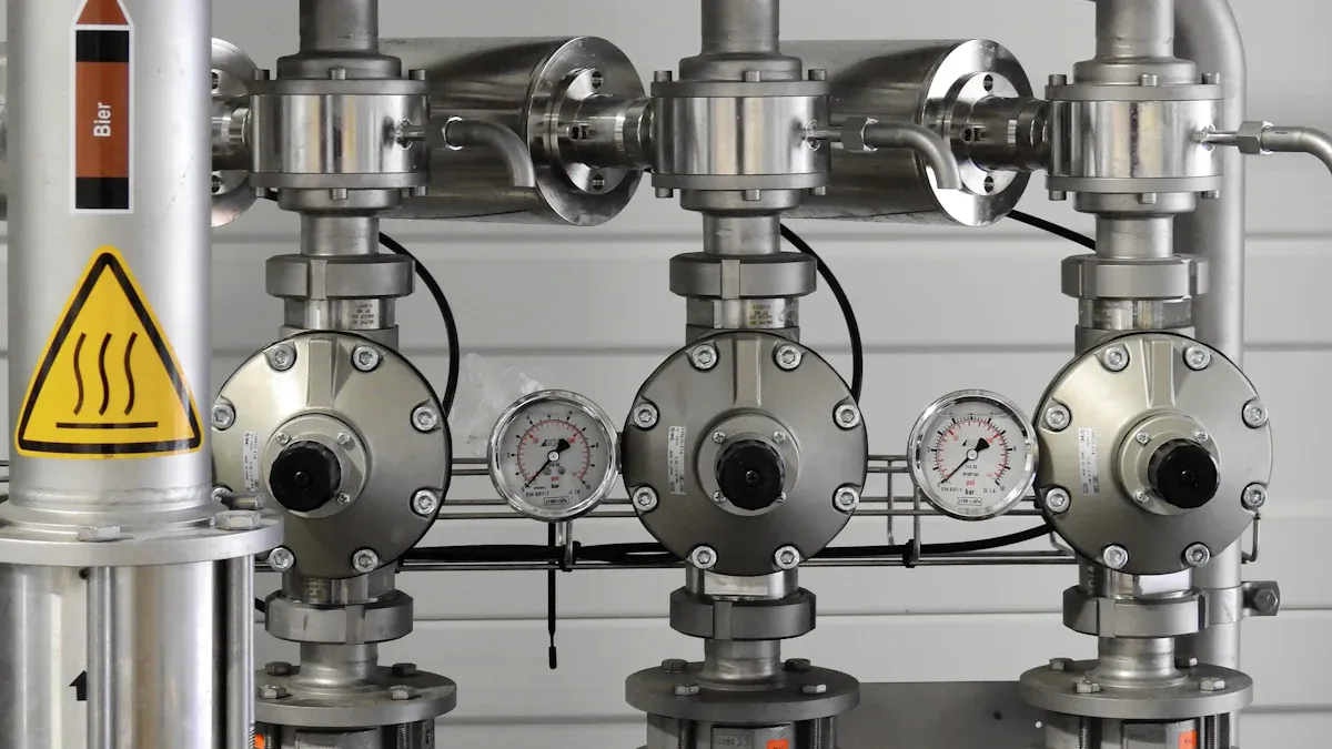
Improper piping and porting significantly hinder a hydraulic safety valve’s ability to function correctly. These issues create resistance and pressure drops, which prevent the valve from responding as intended.
Undersized Inlet or Outlet Lines
Using lines that are too small for the required flow rate creates a bottleneck. Undersized inlet lines restrict the flow of fluid to the valve, delaying its opening or reducing its capacity when needed. Similarly, undersized outlet lines prevent the rapid discharge of fluid, causing back pressure to build up. This back pressure can interfere with the valve’s operation, making it less effective at relieving system overpressure. The system cannot efficiently manage pressure spikes.
Excessive Bends and Fittings
Too many bends and fittings in the piping system introduce significant resistance to fluid flow. Each bend or fitting creates turbulence, leading to additional pressure loss. Engineers refer to these as “minor losses,” but they can be substantial. For example, a pipe with four 90-degree bends can experience nearly double the head loss of a straight pipe. This demonstrates that “minor” losses can significantly impact overall system performance. Minimizing pipe length and the number of fittings reduces friction and energy requirements. Avoiding sharp bends is crucial; sweep elbows offer a better alternative as they cause less flow disruption and pressure loss.
Incorrect Port Connection
Connecting a hydraulic safety valve to the wrong ports is a fundamental error. Each valve has designated inlet and outlet ports. Reversing these connections or connecting the valve to an inappropriate part of the hydraulic circuit prevents it from sensing system pressure correctly or discharging fluid effectively. This mistake can lead to the valve failing to open when pressure is too high or opening unnecessarily, compromising the entire system’s safety and operational integrity.
Contamination During Hydraulic Safety Valve Installation
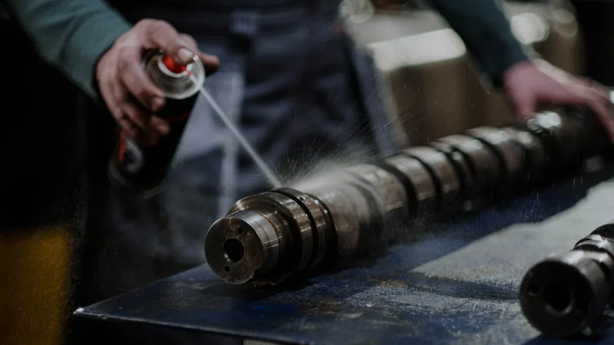
Contamination during installation severely compromises a Hydraulic Safety Valve’s performance. Foreign particles can obstruct internal mechanisms, leading to valve malfunction or failure. Preventing contamination is crucial for reliable operation.
Introduction of Debris
Introducing debris into the hydraulic system during installation is a common mistake. Metal shavings, dirt, dust, or even lint from rags can enter the valve or piping. These contaminants can scratch precision surfaces, clog small orifices, or prevent the valve’s poppet from seating correctly. A valve that cannot seal properly will leak, causing pressure loss and rendering it ineffective in an overpressure event. Technicians must handle all components in a clean environment.
Improper Flushing Procedures
Failing to flush the hydraulic system properly before installing the valve allows existing contaminants to remain. New systems often contain manufacturing residues like welding slag, scale, or machining chips. Older systems accumulate sludge and wear particles. An inadequate flushing procedure leaves these harmful substances in the fluid. When the system operates, these particles circulate and can lodge in the sensitive parts of the Hydraulic Safety Valve, impairing its function. Proper flushing removes these internal contaminants, ensuring a clean operating environment for the valve.
Using Unclean Tools
Using unclean tools during installation also introduces contaminants. Tools covered in grease, dirt, or metal filings can transfer these substances directly into the valve or its connections. For example, a dirty wrench can deposit grit into a port. This seemingly minor oversight can have significant consequences. Always clean tools thoroughly before use. Technicians should also wear clean gloves to prevent transferring skin oils or dirt into the system. Maintaining cleanliness throughout the installation process is paramount for the valve’s long-term reliability.
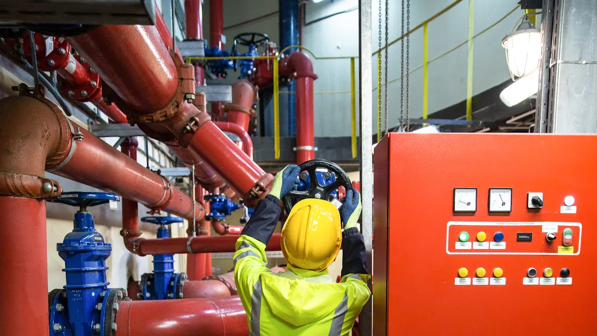
Improper Mounting and Orientation of Hydraulic Safety Valve
Incorrect mounting and orientation significantly impair a hydraulic safety valve’s effectiveness. These errors can prevent the valve from operating correctly, leading to system failures or safety hazards.
Mounting Against Gravity
Mounting a safety valve against gravity, such as horizontally or upside down, creates serious problems. This practice can violate regulations, potentially causing operational delays if authorities tag the valve. A non-vertical orientation also hinders proper drainage within the valve. Furthermore, it negatively impacts the valve’s performance, affecting seat tightness, operational reliability, and set pressure. Such improper installation can lead to leakage and introduce safety hazards.
Incorrect Valve Position
Placing the valve in an incorrect position within the hydraulic circuit compromises its ability to sense pressure accurately. For example, installing a valve too far from the protected component can delay its response. This delay allows pressure to build excessively before the valve activates. Operators must follow manufacturer guidelines for optimal placement.
Insufficient Support and Pipe Stress
Lack of adequate support for the valve and its connected piping introduces harmful stress. Unsecured pipes can exert bending forces on the valve body, leading to misalignment or damage. This stress can cause leaks at connections or even structural failure of the valve itself. Proper pipe supports prevent undue strain on the valve.
Valve Misalignment Issues
Misalignment between the valve and its connecting pipes creates internal stresses and potential leaks. When pipes do not align perfectly with the valve ports, installers must force connections. This forcing can deform the valve body or damage sealing surfaces. Misalignment compromises the integrity of the entire connection, leading to pressure loss and reduced valve reliability.
Overtightening or Undertightening Hydraulic Safety Valve Connections
Improper tightening of connections significantly impacts a hydraulic system’s integrity. Both overtightening and undertightening create distinct problems, compromising safety and performance. Installers must apply precise torque to ensure reliable operation.
Damaging Valve Components
Overtightening connections can cause irreversible damage to valve components. Excessive force distorts the valve body or threads. This damage often renders the valve unusable.
Overtightening a valve at its end connections can cause damage, rendering it unusable for reinstallation.
Such damage leads to costly replacements and system downtime. Installers must avoid applying excessive force.
Causing Leaks and Pressure Drops
Undertightened connections lead to leaks and pressure drops. Loose fittings allow hydraulic fluid to escape, reducing system efficiency. This also permits contaminants to enter the system.
| Cause of Leak/Pressure Drop | What to Look For | Consequences |
|---|---|---|
| Leaks and Loss of Pressure | Hydraulic fluid leaking from the connection, noticeable drop in system pressure. | Significant pressure loss affecting system efficiency; contaminants entering the system, potentially damaging pumps, valves, and seals. |
| Vibration-Induced Loosening | Fittings loosening over time in vibrating systems (e.g., machinery, vehicles). | Further leaks, or complete separation under pressure, leading to system failure and potential hazards. |
| Poor Fluid Flow | Gaps or misalignments between the fitting and the hose/pipe, restricting fluid flow. | Decreased system performance, wasted energy, potential damage to components like valves, pumps, or actuators. |
| Contamination of the Hydraulic System | Dirt, dust, and other contaminants entering the system, especially if fluid is leaking around the connection. | Wear on components, blockages, and potential complete system failure. |
Loose connections also increase the risk of complete separation under pressure. This poses a significant safety hazard.
Using Incorrect Torque Specifications
Using incorrect torque specifications is a common installation error. Manufacturers provide specific torque values for each connection type and size. Adhering to these specifications prevents damage and ensures a secure seal.
| NPTF Threads | Foot Pounds (ft. lbs.) |
|---|---|
| 1/8-27 | 5 to 7 |
| 1/4-18 | 12 to 16 |
| 3/8-18 | 14 to 32 |
| 1/2-14 | 32 to 40 |
| 3/4-14 | 40 to 48 |
| 1-11 1/2 | 52 to 60 |
| Thread Size | Plug or Fitting Size | Foot Pounds (ft. lbs.) |
|---|---|---|
| 7/16-20 | -4 | 10 to 15 |
| 9/16-18 | -6 | 17 to 21 |
| 3/4-16 | -8 | 30 to 35 |
| 7/8-14 | -10 | 30 to 35 |
| 1 1/16-12 | -12 | 30 to 35 |

These tables provide industry standards for NPTF and SAE ports. Installers must consult these guidelines.
- NPT Safety Heads
- Safety Heads These components require precise torque. Ignoring these values can lead to cracked castings, especially with 3/4″ NPTF work ports.
Improper Sealing Material Application
Incorrect application of sealing materials also causes problems. Using too much or too little thread sealant can lead to leaks. Excess sealant can enter the system, causing contamination or blockages. Insufficient sealant results in an incomplete seal. Installers must apply sealants according to manufacturer instructions. This ensures a tight, leak-free connection.
Neglecting Pre-Installation Checks for Hydraulic Safety Valve
Ignoring pre-installation checks significantly jeopardizes a system’s safety and operational efficiency. These oversights can lead to premature failure or dangerous malfunctions. Proper verification before installation prevents costly errors.
Skipping Valve Inspection
Installers sometimes skip a thorough visual inspection of the valve. This oversight can miss manufacturing defects, shipping damage, or foreign objects inside the valve. A damaged or obstructed valve cannot perform its critical safety function. Always inspect the valve for any visible issues before proceeding with installation.
Ignoring System Compatibility
Failing to consider system compatibility is a major error. Engineers must verify several critical system parameters. These include:
- Operating pressure
- Temperature range
- Fluid compatibility
- Response time
- Mounting and size
- Operational modes
- Material and design considerations
- Valve sizing and Cv calculations
- Pressure ratings
- End connections
Material and design considerations are crucial. They encompass material compatibility with the hydraulic fluid and contaminants, corrosion resistance, and structural integrity. Sealing elements must prevent leaks and offer durability. Materials must tolerate the expected temperature range.
Failing to Verify Specifications
Not verifying valve specifications against system requirements creates significant risks. If a valve is not correctly integrated, it can cause excessive heat buildup and energy waste. For example, a valve restricting flow can force a relief valve to open, diverting fluid at high pressure and generating substantial heat. This heat can severely damage hydraulic components. Other risks include:
- High-pressure fluid injection from small leaks.
- Burns and fire risks from hot fluid or petroleum-based fluids.
- Mechanical hazards from sudden equipment movement.
- Chemical exposure from toxic fluid compounds.
Selecting the Wrong Valve Type or Size
Choosing an incorrect valve type or size compromises system protection. Several criteria guide proper selection:
- Set pressure: This must not exceed the system’s maximum allowable working pressure (MAWP).
- Back pressure: Consider the pressure on the outlet side.
- Blow-off capacity: The valve must discharge fluid at the required rate.
- Temperature: Match the valve to the system’s operating temperature.
- Valve and seal material: These must be compatible with the fluid and conditions.
The actuator’s ability to generate sufficient torque to operate the valve at minimum supply pressure is also important. It must safely handle maximum potential pressure.
Lack of Proper Documentation and Labeling for Hydraulic Safety Valve
Poor documentation and labeling practices severely hinder effective system management. They create confusion, increase the risk of operational errors, and complicate maintenance. Proper records and clear identification are essential for safety and efficiency.
Missing Pressure Settings
Operators often fail to record the set pressure for safety valves. This omission creates significant risks. Without documented settings, technicians cannot verify if a valve protects the system correctly. They might inadvertently adjust the valve to an unsafe pressure during maintenance. This lack of information compromises the system’s ability to prevent overpressure, potentially leading to equipment damage or failure.
Inadequate Identification
Inadequate identification of valves makes system management difficult. A valve chart summarizes important valve information, and facilities should post it near critical equipment. This helps employees and support personnel. Color-coded valve tags align with existing standards for hazards, or they can communicate specific identification. A consistent numbering system provides clear identifiers for each valve based on its location. This standardizes equipment and reduces misidentification. Tagging valves also allows for barcodes and other identifying information to semi-automate asset management processes. Valve tags highlight safety warnings through specific colors or information. They communicate potential dangers, facilitate maintenance, and help prevent human error. Standards like ANSI/ASME A13.1 and NFPA99 provide guidelines for pipe and valve marking. These standards recommend specific color codes for identifying marks, such as white text on a red background for fire-quenching fluids. Different tag types exist for chemical, waste/water, and gas pipes, along with Lock Out, Tag Out (LOTO) tags for worker safety.
Poor Maintenance Records
Poor maintenance records prevent effective troubleshooting and long-term system health. Without a history of inspections, repairs, and adjustments, technicians cannot track valve performance or identify recurring issues. This makes it difficult to schedule preventive maintenance or diagnose problems accurately. Comprehensive records ensure accountability and support continuous improvement in system reliability.
Meticulous installation of a hydraulic safety valve is paramount. Correctly installing these valves ensures machinery safety, efficiency, and longevity. This attention to detail prevents pressure spikes, minimizes wear, and reduces downtime. It also guarantees precise pressure regulation and consistent performance. Continuous training and adherence to best practices are essential for system integrity.
FAQ
How does incorrect pressure setting affect a hydraulic system?
Incorrect pressure settings cause premature valve activation or failure to protect against overpressure. This leads to system inefficiencies, reduced lifespan, and potential catastrophic failures.
Why is proper piping crucial for hydraulic safety valves?
Proper piping ensures the valve responds correctly. Undersized lines or excessive bends create resistance. This prevents the valve from effectively relieving system overpressure.
What are the risks of contamination during valve installation?
Contamination introduces debris. This debris can scratch surfaces, clog orifices, or prevent proper sealing. Such issues lead to leaks, pressure loss, and valve malfunction.
Post time: Dec-18-2025