
An incorrect Solenoid Valve selection frequently results in costly operational failures and increased maintenance expenditures. This critical decision directly impacts productivity. Conversely, a proper choice ensures robust system reliability and enhances overall efficiency across the manufacturing line.
Key Takeaways
- Choose the right solenoid valve by understanding what it will control. Match the valve’s materials to the liquid or gas it handles. This prevents damage and keeps your system working well.
- Consider how the valve works by default. Decide if it should be open or closed when there is no power. This choice affects safety and how your system runs.
- Think about the environment where the valve will be. Check its protection rating against dust and water. This helps the valve last longer and prevents electrical problems.
Understanding Your Application for Solenoid Valve Selection
Identifying Media Type and Compatibility for Your Solenoid Valve
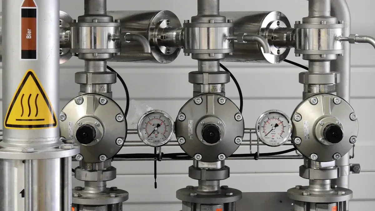
Selecting the correct Solenoid Valve begins with a thorough understanding of the media it controls. Different fluids and gases require specific valve materials to prevent corrosion, degradation, and operational failure. For instance, standard brass valves with NBR seals work well for air and inert gases. However, light oil often requires FKM seals, and steam applications demand brass, bronze, or stainless steel with PTFE seals for high temperatures. Very aggressive media, such as strong acids or alkalis, necessitate a dry armature design. This design ensures only the valve body and seal contact the media, protecting internal components.
Determining Normally Open vs. Normally Closed Solenoid Valve Operation
Manufacturers must decide between normally open (NO) and normally closed (NC) valve operations. This choice depends on the system’s default state and safety requirements.
| Feature | Normally Open (NO) Solenoid Valve | Normally Closed (NC) Solenoid Valve |
|---|---|---|
| Default State | Open (fluid passes when not energized) | Closed (fluid is shut off when not energized) |
| When Energized | Closes (electrical signal overcomes spring/fluid pressure) | Opens (electrical signal overcomes spring force) |
| Spring Position | Spring holds the valve open (under the armature) | Spring holds the valve closed (on top of the armature) |
| Fluid Pressure | Assists in holding the valve open; solenoid must overcome it to close | Assists in holding the valve closed; solenoid must overcome it to open |
Normally open valves allow fluid flow without power, suitable for systems needing automatic fluid control, like irrigation. They offer fast response times. Conversely, normally closed valves remain shut unless energized. They serve as a critical safety measure, especially during power cuts, preventing leaks in applications such as fuel lines or burner controls.
Choosing Between Direct Acting and Pilot Operated Solenoid Valves
The choice between direct-acting and pilot-operated valves depends on flow requirements and pressure differentials. Direct-acting valves transfer electromagnetic forces directly to the valve mechanism. They are versatile and common in universal applications for neutral and clean liquids, vapors, and gases. These valves are suitable for:
- Shut-off, dosing, filling, and ventilation tasks.
- Negative pressure circuits.
- Applications with particle debris.
- Cost-effective compact and miniature versions for high pressures. Direct-acting valves offer fast response times and precise control, making them ideal for hydraulics, pneumatics, and automated production lines.
Key Technical Specifications for Your Solenoid Valve
Calculating Flow Rate (Cv/Kv Value) for Your Solenoid Valve
Accurate flow rate calculation is essential for optimal system performance. Engineers use the Kv factor as a standardized measure for fluid flow through a valve. They calculate it using water at a pressure drop of approximately 1 bar and a temperature of 5-30°C, with the unit m³/h. The Cv value is the US measurement unit, given in USG/min (US-Gallon per minute). Conversion formulas exist: Kv = 0.857 * Cv and Cv = 1.165 * Kv. To calculate the valve flow coefficient (Cv) for liquids, use the formula: Cv = Q * sqrt(SG / P). Here, Q represents the flow rate in gallons per minute (GPM), SG is the specific gravity of the fluid, and P is the pressure drop in pounds per square inch (psi).
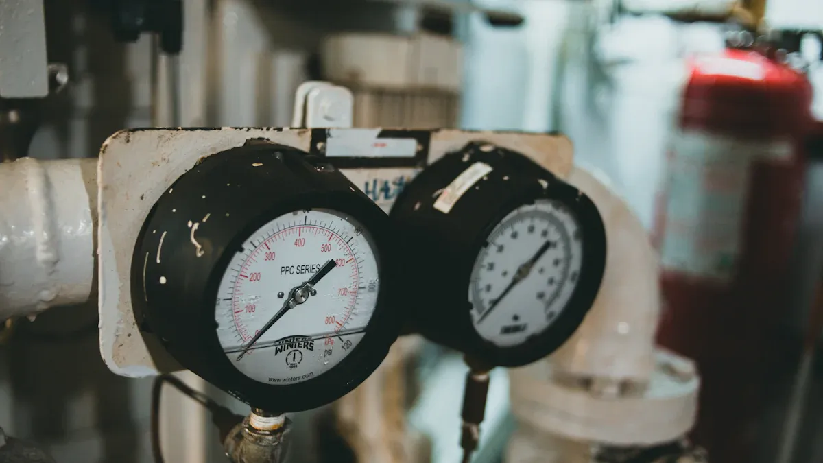
Matching Pressure Ratings for Your Solenoid Valve
Selecting a Solenoid Valve that precisely matches the system’s required pressure and flow rate is crucial. Mismatching pressure ratings can lead to several issues. If the rated working pressure is excessively high, it increases financial investment. Conversely, if the chosen rated working pressure is too low or closely matches the actual medium pressure, it can cause accidents due to insufficient structural strength. For systems operating under high pressure, choosing reinforced diaphragm or piston-style valves ensures proper function and durability.
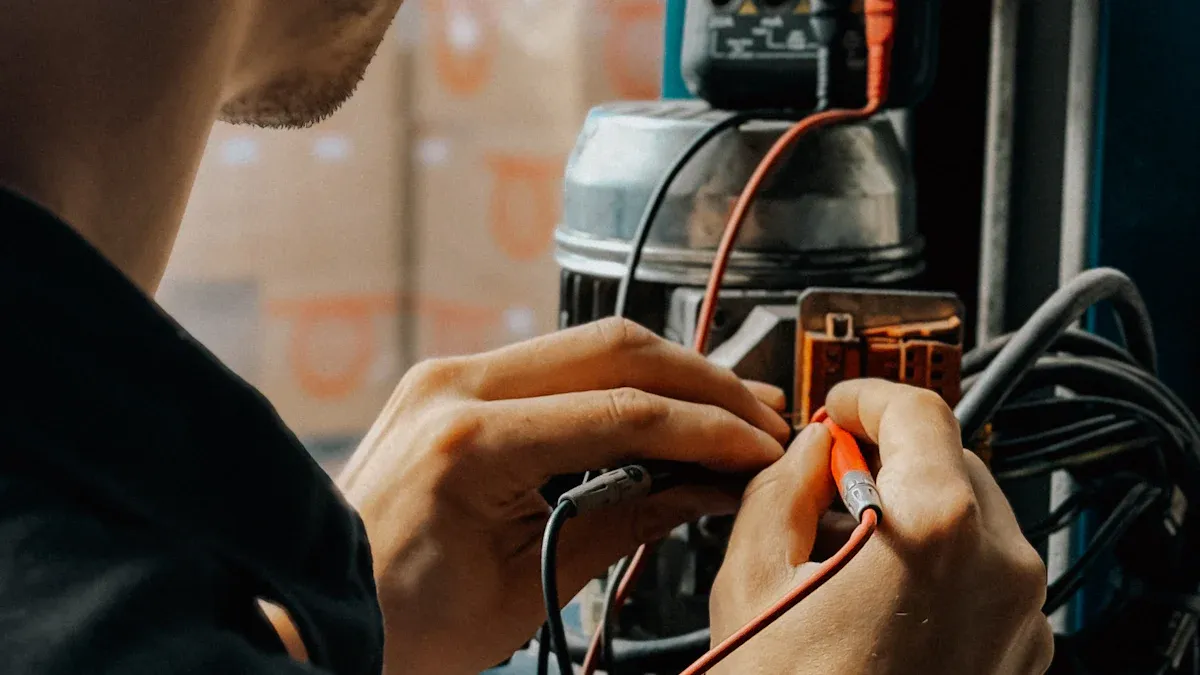
Selecting the Correct Voltage and Power for Your Solenoid Valve
Industrial solenoid valves typically operate on either AC (alternating current) or DC (direct current) voltage. AC voltage, common in industrial settings, often ranges from 110V to 240V, suitable for larger valves. DC voltage is used in low-power applications and offers stability and precise control, with common ranges from 12V to 24V. The specific voltage needed varies based on valve size, application type, and model. Common voltage options include 12V DC, 24V DC, 110V AC, and 240V AC.
Ensuring Material Compatibility (Body and Seal) for Your Solenoid Valve
Material compatibility for the valve body and seals prevents premature wear and failure. NBR (Nitrile Buna Rubber) seals are common, suitable for most neutral fluids and gases. They offer good resistance to aging with heat and abrasion. NBR works well with water, air, fuels, and oils, but has poor resistance to ozone, acetone, and chlorinated hydrocarbons.
| Material | Water | Oil | Gas | Acids |
|---|---|---|---|---|
| Viton | Good | Excellent | Fair | Good |
| PTFE | Excellent | Good | Excellent | Excellent |
| NBR | Fair | Excellent | Fair | Poor |
| EPDM | Excellent | Poor | Good | Fair |
For valve bodies, materials like brass offer good general corrosion resistance. Stainless steel, particularly 316, provides excellent corrosion resistance for valve bodies, stems, and balls.
Environmental and Safety Considerations for Solenoid Valve Use
Assessing Temperature Range for Your Solenoid Valve
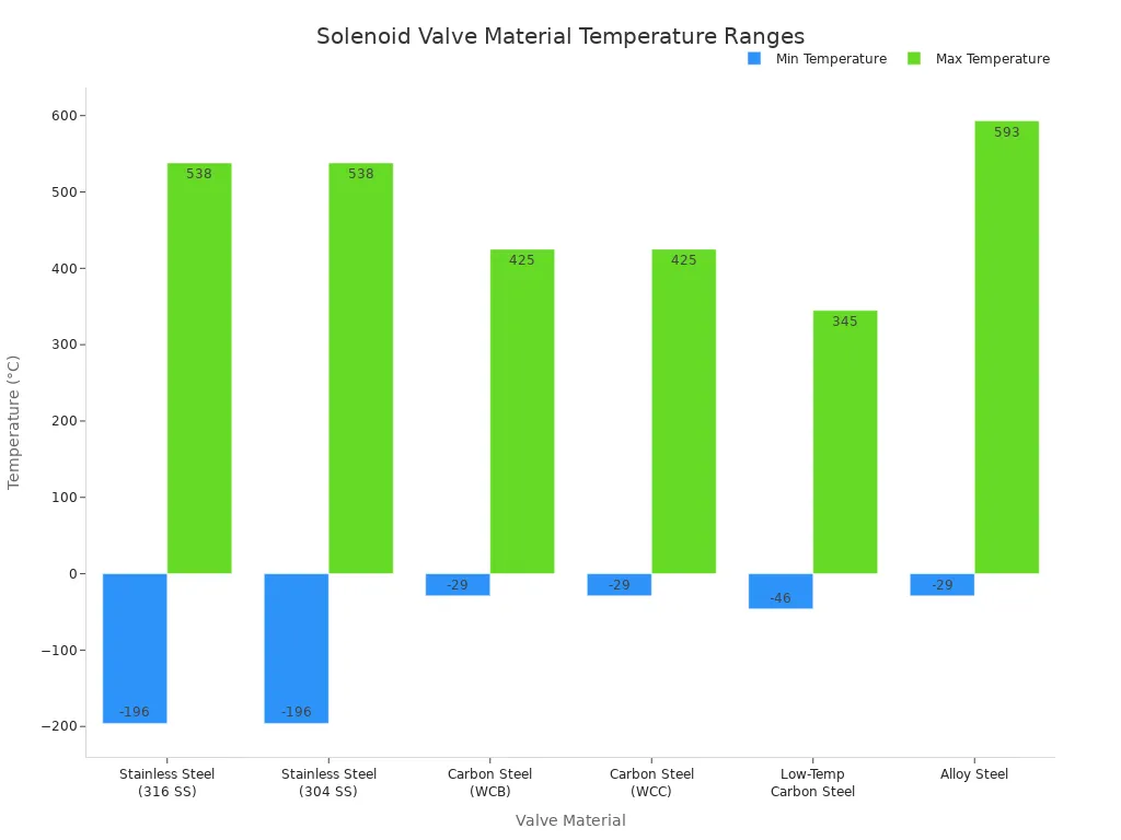
Operating environments significantly impact valve performance and longevity. Manufacturers must consider the temperature range where the valve will function. Extreme temperatures can degrade materials, leading to leaks or complete failure. Different valve body materials and seal materials have specific temperature limits.
| Valve Material | Min Temperature (°C/°F) | Max Temperature (°C/°F) |
|---|---|---|
| Stainless Steel (316 SS) | -196°C (-320°F) | 538°C (1000°F) |
| Stainless Steel (304 SS) | -196°C (-320°F) | 538°C (1000°F) |
| Carbon Steel (WCB) | -29°C (-20°F) | 425°C (800°F) |
| Carbon Steel (WCC) | -29°C (-20°F) | 425°C (800°F) |
| Low-Temp Carbon Steel | -46°C (-50°F) | 345°C (650°F) |
| Alloy Steel | -29°C (-20°F) | 593°C (1100°F) |
Seal materials also have critical temperature considerations:
- PTFE (Polytetrafluoroethylene): It offers high temperature resistance and chemical inertness. This makes it suitable for severe chemical resistance applications.
- EPDM (Ethylene Propylene Terpolymer): This material resists acids, alkalis, and salts up to 90°C. It is not suitable for oils, petrochemicals, or concentrated acids.
- NBR (Nitrile Rubber): It provides high chemical resistance to oils and petroleum. It also has excellent abrasion resistance. It is weak against oxidizing media like acids.
- FKM/FFKM (Fluorinated Elastomer/Perfluoro Elastomer): These provide more chemical and temperature resistance than NBR. Some FFKM grades perform continuously above 200°C.
- PPS (Polyphenyl Sulphide): This material performs above 200°C. It resists acids, alkalis, and abrasion. Manufacturers use it as a valve body material.
- PVDF (Polyvinylidene Fluoride): It resists solvents, acids, and bases. It is not suitable for applications requiring high temperature resistance.
- PEEK (Polyether Ether Ketone): This material has excellent mechanical and chemical properties. It offers superior quality as a valve body material.
Understanding Ingress Protection (IP) Ratings for Your Solenoid Valve
Ingress Protection (IP) ratings indicate a valve’s resistance to solids and liquids. This rating ensures environmental suitability. It enhances durability and reduces maintenance. It also prevents electrical hazards. Manufacturers choose valves with appropriate IP ratings based on specific environmental conditions. Outdoor settings, for example, require high water resistance (e.g., IP67 or IP68). Higher IP ratings generally mean better seals and construction. This leads to increased durability and less maintenance. Correctly rated valves are essential for safety. They prevent electrical hazards from water ingress, especially in dangerous environments.
| IP Rating | Protection Against Solids | Protection Against Liquids | Suitable Environments |
|---|---|---|---|
| IP54 | Dust ingress | Splashing water | General applications |
| IP64 | Dust-tight | Splashing water from all directions | General applications |
| IP65 | Dust-tight | Water jets | Outdoor applications (rain, dust) |
| IP67 | Dust-tight | Immersion up to 1 meter | Environments with temporary submersion |
| IP68 | Dust-tight | Continuous immersion beyond 1 meter | Underwater applications, flood-prone areas |
Specifying Hazardous Area Certifications for Your Solenoid Valve
Certain industrial environments contain explosive atmospheres. These require specialized certifications for equipment like solenoid valves. These certifications ensure safety and prevent explosions.
- UL Certification: This indicates compliance with safety and compliance standards for North America (United States and Canada).
- CE Marking/ATEX Certification: This is required for the European Union market. It specifically certifies safety for potentially explosive environments. This includes flammable gases and vapors.
- CSA Certification: This signifies adherence to Canadian Standards Association specifications. It is also accepted in certain hazardous applications in the US.
- IECEx Certification: This is an international certification from the International Electrotechnical Commission. It applies to equipment used in explosive atmospheres and is accepted globally.
Solenoid valves designed for hazardous areas often carry ATEX and IECEx approvals. ATEX is the European standard for equipment operating in potentially explosive atmospheres. It defines risk severity and protection types to prevent explosions. Products must undergo testing by a registered notified body to gain ATEX certification. This covers both flammable gas and dust environments for electrical and non-electrical ignition sources.
Implementing Fail-Safe Mechanisms with Your Solenoid Valve
Fail-safe mechanisms are crucial for system safety during power loss. These include de-energize-to-trip (DTT) and energize-to-trip (ETT) philosophies. DTT is generally more common and safer. ETT systems require compliance with specific integrity clauses (61511-1, Clause 11.6.2). This ensures circuit and power supply integrity. Redundancy schemes like 1oo2, 2oo2, 2oo3, and even 2oo4 (in hydraulic systems) are also employed. Advanced redundancy schemes such as 2oo2D/1oo1HS, 2oo2, 1oo2, and 2oo3 are available as packaged or OEM equipment. They often include online testing capabilities. Smart solenoid systems, like Emerson’s DVC-6200SIS and Neles’ ValvGuard VG9000, offer enhanced online testing capabilities. This includes partial-stroke testing. They collect and store test data for the solenoid and valve assembly.
Latching solenoids with fail-safe controls provide a robust solution for system safety during power loss. These solenoids move to a predetermined ‘safe’ position upon power failure. An integrated capacitive discharge circuit achieves this. When power is present, the capacitor charges in parallel with the solenoid. If power is lost, the capacitor discharges. It provides the necessary energy to move the armature to the designated safe position. This mechanism ensures the solenoid can still actuate to a safe state, even with a complete power cut. An example is disconnecting a battery in an EV during a collision. The most reliable implementation involves mounting the fail-safe control directly on the solenoid. This prevents issues if power wires are damaged.
Practical Aspects of Solenoid Valve Installation and Maintenance
Selecting Port Size and Connection Type for Your Solenoid Valve
Manufacturers select port size and connection type for proper fluid transfer. Various standards define pipe sizes and pressure ratings.
| Standard | Class/Code | Pipe Sizes (inches) | Pressure Rating |
|---|---|---|---|
| ANSI/ASME B16.5 | Class 150-2500 | 1/4″ to 24″ | N/A |
| DIN 1092-1/ISO 7005 | N/A | DN 10 to DN 2000 | PN 2.5 to PN 100 bar |
| SAE J518 | Code 61/62 | 1/4″ to 24″ | 3000/6000 psi |
Electrical connector types also vary.
| Connector Type | Pin Spacing | Typical Pins | Common Thread Types |
|---|---|---|---|
| Form A | 18 mm | 2 or 3 | PG 9, PG 11, M16, NPT 1/2 in |
| Form B (Micro) | 10 mm or 11 mm | 1 flat-blade & 2 U-shaped (10mm), 3 flat-blade (11mm) | PG 9, NPT 1/2 in |
| Form C (Sub-micro) | 8 mm or 9.4 mm | 2 or 3 | PG 7 |
| M12 | N/A (compact) | N/A | N/A |
| DIN 43650 | N/A (widely-used) | N/A | N/A |
These specifications ensure compatibility and secure connections.
Considering Mounting Orientation and Space for Your Solenoid Valve
Mounting orientation impacts valve performance and lifespan. It influences drainage, plunger seating, and response time. Compact valve bodies suit confined panels; larger dissipative housings need sufficient airflow. Exceeding space allowances around coils increases internal temperature, causing premature coil degradation. Sediment or particles cause coil failure. An upstream filter prevents impurities. Vertical mounting of the coil and armature minimizes sediment risk.
Planning Maintenance Requirements for Your Solenoid Valve
A proactive maintenance plan prevents failures. Before installation, ensure power supply matches coil specifications and proper ventilation. Do not power a new coil until securely mounted. Regularly inspect seals, O-rings, and membranes for damage; clean dirt particles from pipe connections. Use appropriate voltage, frequency, and surge protection. Perform visual inspections for corrosion or leakage. Functional testing verifies actuation timing. Conduct leak checks and cycle testing regularly, logging all activity. Pre-schedule replacement of seals or diaphragms. Always disconnect power and depressurize the system before servicing. Clean and inspect internal components, replacing worn parts. Test the valve for leaks and correct operation.
Evaluating Expected Lifespan and Durability of Your Solenoid Valve
Several factors influence expected lifespan and durability. High-quality materials, optimized design, and lubrication systems enhance wear resistance. Electronic control and monitoring systems optimize operation. High-frequency use, sealing technology, and fluid interaction present challenges. Stable electrical supply, surge protectors, regular cleaning, and filter installation are crucial. Proper ventilation, avoiding over-voltage, and correct installation prevent premature failure of the Solenoid Valve.
Avoiding Common Mistakes in Solenoid Valve Selection
Not Accounting for Pressure Spikes in Your Solenoid Valve System
Manufacturers often overlook pressure spikes, a critical error. Pressure transients, like water hammer from rapid valve operation, damage the valve and other system components. Fluctuating system pressures alter the force needed for valve actuation, impacting response times and overall system performance. High-pressure environments demand valves that endure extreme forces without compromising sealing. This increases leakage and potential system failures. Overpressure events lead to catastrophic failures such as valve rupture or seat damage. Underpressure scenarios cause inadequate sealing or valve chatter. The interaction of fluid dynamics and valve operation results in cavitation, erosion, and flow-induced vibration, leading to premature valve failure or reduced performance.
Overlooking Seal Material Degradation for Your Solenoid Valve
Ignoring seal material degradation presents another common mistake. Seals are crucial for preventing leaks and maintaining system integrity. Over time, exposure to media, temperature fluctuations, and operational stress can cause seals to harden, crack, or lose elasticity. This degradation compromises the valve’s ability to seal effectively, leading to leaks and potential system contamination. Regular inspection and appropriate material selection for seals are essential to prevent these issues.
Ignoring Environmental Factors Affecting Your Solenoid Valve
Environmental factors significantly impact valve longevity and performance. Manufacturers must verify the IP protection rating of the valve if it will be exposed to moisture. They should consider using external enclosures to shield the coil in certain conditions. In colder environments, most incompressible fluids become thicker, leading to sluggish performance and slower valve response time. Extremely cold temperatures reduce seal elasticity, causing them to become brittle and potentially fail to conform to the valve seat, increasing leak risk. Metals and elastomers contract in cold temperatures, which negatively affects sealing ability. When a valve operates infrequently in cold conditions, the elastomer’s seal may not compress to the mating surface, resulting in slower actuation.
Prioritizing Initial Cost Over Long-Term Performance of Your Solenoid Valve
Prioritizing initial cost over long-term performance is a frequent pitfall. While a lower upfront cost seems attractive, it often leads to higher total cost of ownership (TCO). Branded or OEM valves, despite a higher initial cost, offer consistent performance, better longevity, and reliable warranty support. They also handle pressure better. Conversely, local or unbranded options often provide inconsistent performance and lack warranty support. Domestic RO valves might last 1–2 years, while industrial valves typically last 3–5 years, and high-end valves up to 10 years with proper maintenance. Ignoring signs like inconsistent water flow, loud buzzing, or overheating leads to delayed replacement, potentially damaging other system components. Investing in a high-quality valve leads to significant long-term savings by reducing energy consumption, maintenance, replacement costs, and downtime.
A systematic approach to valve selection is crucial for manufacturing success. This involves considering valve design, electrical specifications, maintenance, and total cost of ownership. Informed decisions lead to quick start/stop functions, adaptability to various media, and extended service life. These benefits enhance process reliability and cost-effectiveness. For complex applications, consulting experts ensures optimal system performance.
FAQ
What is the primary function of a solenoid valve?
A solenoid valve controls fluid flow in a system. It uses an electrical current to open or close a valve, automating fluid management.
Why is material compatibility important for solenoid valves?
Material compatibility prevents corrosion and degradation. It ensures the valve’s longevity and reliable operation with specific media.
How do IP ratings affect solenoid valve selection?
IP ratings indicate protection against solids and liquids. They ensure the valve suits its environment, preventing damage and electrical hazards.
Post time: Oct-29-2025