
Engineers must understand the critical technical factors for optimal solenoid coil selection. They systematically approach solenoid coil selection for specific application requirements. This ensures meeting performance criteria and manufacturing constraints with the right Solenoid Coil. A precise selection process leads to reliable product development.
Key Takeaways
- Engineers must define core needs for a solenoid coil. This includes force, stroke, and how often it works. This step helps the coil fit well and work right.
- Engineers must check electrical parts like voltage and current. They also need to think about heat and insulation. This makes sure the coil works well and lasts a long time.
- Engineers must consider the environment where the coil will be used. This includes temperature, moisture, and vibrations. This helps the coil stay strong and work for many years.
Defining Core Application Requirements for Your Solenoid Coil
Engineers begin the solenoid selection process by thoroughly defining core application requirements. This foundational step ensures the chosen component integrates seamlessly and performs reliably within the larger system. Precise specification at this stage prevents costly redesigns and performance issues later.
Required Force and Stroke
Design engineers must first determine the precise force a solenoid needs to generate. They also specify the distance the plunger must travel, known as the stroke. These two fundamental parameters directly influence the solenoid’s physical size and electrical power requirements. An accurate assessment prevents oversizing or undersizing the component, which impacts both cost and performance.
Operating Cycle and Duty Cycle
The operating cycle describes how frequently the solenoid activates. Duty cycle refers to the ratio of “on” time to the total cycle time. For solenoid coils in continuous industrial applications, an application is considered continuous duty if the ‘On Time’ approaches or exceeds the 30-minute thermal stabilization time. Continuous duty means the coil remains ‘On continuously without interruption for periods of about 30 minutes or longer.’ In such cases, the maximum wire temperature can reach approximately 120 degrees Celsius, as observed for ‘On Time/Off Time’ periods of 30 minutes to 1 hour. This thermal consideration is critical for coil longevity and preventing premature failure.
Response Time Specifications
Many applications demand rapid actuation. Engineers must define the required time for the solenoid to activate and deactivate. Fast response times often necessitate specific coil designs and power delivery systems. Slow response can lead to system inefficiencies or operational failures, especially in time-critical processes.
Physical Space Constraints
The physical dimensions available for the solenoid are often a primary constraint. Solenoids must fit within the available physical space. For locking mechanisms, solenoids often need to fit within standard lock cutouts, which can be as thin as ½” (12.7mm) or ¾” (19.5mm). Packaging constraints often lead to the need to increase the actuation force within a particular solenoid size to ensure the complete system functions as desired. Solenoids’ compact and lightweight design is advantageous for integration into devices with limited space, such as automotive electrical systems or portable equipment. Minimizing size and weight is a priority in modern technology for improved efficiency and ease of use.
Electrical Parameter Considerations for Solenoid Coil Performance
Engineers must carefully evaluate electrical parameters to ensure optimal solenoid coil performance. These factors directly influence the coil’s efficiency, reliability, and compatibility with the overall system.
Voltage and Current Ratings
Selecting the correct voltage and current ratings is paramount. Automotive solenoid coils, for instance, typically operate on 12V or 24V DC systems. Matching the coil to the vehicle’s electrical system voltage is crucial for proper function and to prevent damage. A 24V coil in a 12V system may produce insufficient magnetic force. Conversely, a 12V coil in a 24V system could overheat and burn out. In automotive applications like fuel injection, current control often uses a ‘peak-and-hold’ waveform. This involves a high ‘Boost Phase’ current for quick actuation, followed by a lower ‘Hold Phase’ current to maintain position with less power.
Resistance and Inductance Values
The resistance and inductance of a solenoid coil significantly affect its electrical behavior. Resistance determines the steady-state current for a given voltage. Inductance influences how quickly the current builds up and decays. For pulsed power applications using a Pulse Width Modulation (PWM) driver, the coil’s inductance greatly impacts both the average current and the ripple current.
Power Consumption and Heat Dissipation
Every solenoid coil consumes electrical power, which converts into mechanical work and heat. Engineers must calculate power consumption to ensure the power supply can meet demand. Effective heat dissipation is critical to prevent the coil from overheating, which can degrade insulation and shorten lifespan.
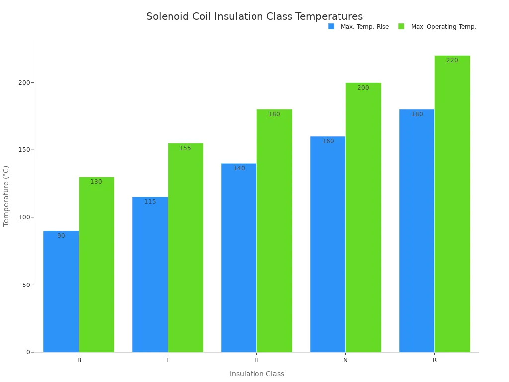
Insulation Class and Dielectric Strength
Insulation protects the coil windings from electrical shorts and environmental factors. Insulation classes define the maximum allowable operating temperature.
| Insulation Class | Allowable Max. Temp. Rise (°C) | Allowable Max. Operating Temp. (°C) |
|---|---|---|
| B | 90 | 130 |
| F | 115 | 155 |
| H | 140 | 180 |
| N | 160 | 200 |
| R | 180 | 220 |
Dielectric strength refers to the insulation’s ability to withstand high voltages without breaking down. Withstand voltage tests apply a specified voltage between power supply and grounding terminals.
| Rated Voltage U (V) | Withstand Voltage and Turn-to-Turn Withstand Voltage Test (V) |
|---|---|
| U < 60 | ≥ 1000 |
| 60 ≤ U < 300 | ≥ 2000 |
| 300 ≤ U < 600 | ≥ 2500 |
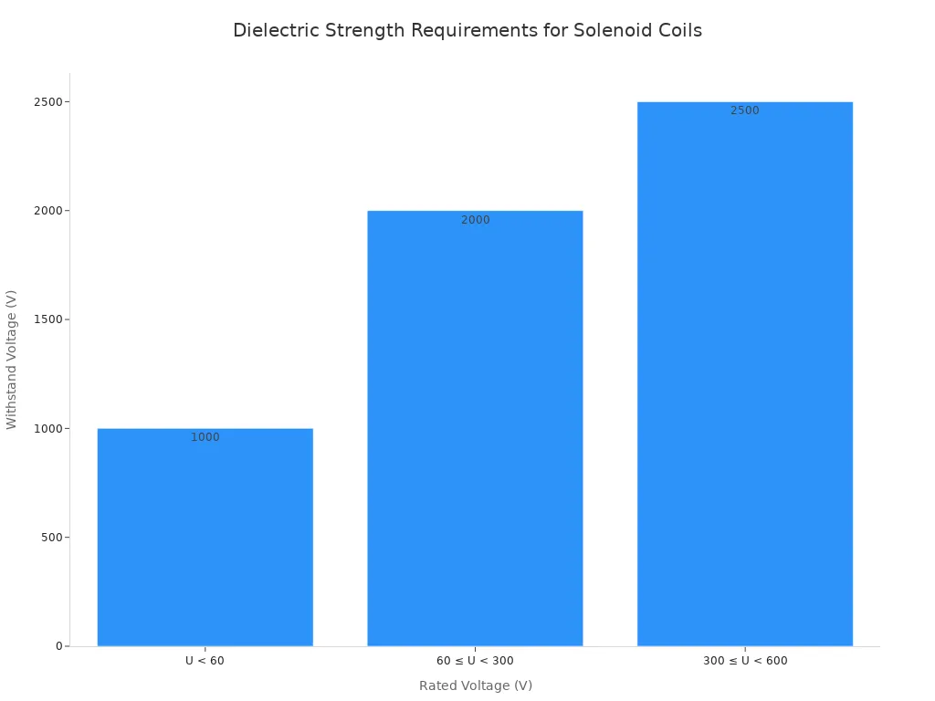
These tests ensure no breakdown or flashover occurs, confirming the insulation’s integrity.
Environmental and Operational Factors Affecting Solenoid Coil Durability
Engineers must consider environmental and operational factors. These elements directly impact a Solenoid Coil‘s durability and long-term performance. Ignoring them can lead to premature failure and increased maintenance costs.
Operating Temperature Range
Extreme temperatures significantly affect solenoid coil performance. High temperatures can degrade insulation materials. Low temperatures can make materials brittle. Engineers must select coils rated for the specific ambient and operational temperature range of the application. This ensures consistent performance and extends the coil’s lifespan.
Exposure to Moisture and Contaminants
Moisture and contaminants pose serious threats to solenoid coils. Water ingress causes corrosion and electrical shorts. Dust and debris can impede plunger movement. For environments with humidity and moisture, engineers select solenoid valves with appropriate enclosure ratings, such as IP65 or higher. They ensure adequate sealing against moisture ingress. This prevents corrosion and electrical faults. Installing an upstream filter also prevents debris, sediment, or particle contamination from entering the valve. This protects the armature’s motion.
Vibration and Shock Resistance
Many applications expose solenoids to significant vibration and shock. Heavy machinery, for example, generates constant movement. Solenoid coils must withstand these forces without malfunctioning. Engineers avoid operating valves in environments with vibrations exceeding 50m/s². This prevents malfunctions. Vibration tests simulate random vibration on heavy-duty equipment. Coils undergo monitoring for 72 hours in each of three perpendicular axes. Operating shock tests simulate sudden, severe shock. Coils must withstand a 5ms pulse of 490 m/sec² (50 g). These tests ensure the coil maintains function, avoids loose parts, and prevents fatigue cracks.
Chemical Compatibility
Chemical exposure can severely damage solenoid coil components. Aggressive chemicals can degrade wire insulation, bobbin materials, and encapsulation compounds. Engineers must identify all chemicals the solenoid might encounter. They then select materials compatible with those substances. This prevents material breakdown and ensures the coil’s integrity.
Material Selection and Construction of the Solenoid Coil
Engineers carefully select materials for a Solenoid Coil. These choices directly influence its performance, durability, and cost. Each component plays a vital role in the coil’s overall function.
Wire Gauge and Type
Copper wire is the most common material for solenoid coils. It offers superior conductivity and flexibility. The wire’s diameter is a critical factor. A thin wire increases resistance, reduces efficiency, and can lead to overheating. Copper wire classes F, H, and N tolerate temperatures above 155°C, 180°C, and 200°C, respectively. This allows effective performance in various temperature conditions. Increasing the number of windings enhances magnetic field power. A decrease in resistance allows more current to flow, creating a stronger magnetic field. Wires in the 22 to 24 AWG range offer a good balance for mid-power applications. Other materials like aluminum, silver, and gold also offer specific advantages for specialized applications. For instance, gold electroplating provides corrosion resistance in aerospace coils.
Bobbin Material Properties
The bobbin provides structural support for the wire windings. Its material must possess excellent dielectric strength to prevent electrical shorts. It also needs high thermal resistance to withstand operational heat. Engineers often choose thermoplastics like nylon or PBT for their good mechanical properties and cost-effectiveness. These materials ensure the coil maintains its shape and electrical integrity under stress.
Encapsulation and Potting Compounds
Encapsulation and potting compounds protect the coil from environmental damage. These materials offer increased performance, enhanced reliability, and improved long-term durability. They provide strong adhesion, thermal stability, and chemical resistance. These compounds also strengthen mechanical integrity, fill voids, and protect against vibration and moisture. Epoxy provides resistance to chemical erosion. Silicone-based gels offer flexibility to handle temperature swings. These compounds are perfect for high voltage coil applications. They offer vibration and shock resistance, moisture and corrosion protection, and exceptional electrical insulation.
Lead Wire and Termination Options
Lead wires connect the solenoid coil to the power source. Engineers select them based on current capacity, flexibility, and insulation requirements. Common termination options include soldered connections, crimped terminals, or integrated connectors. The choice depends on the application’s environment, assembly method, and required reliability. Proper termination ensures a secure and long-lasting electrical connection.
Performance and Reliability Metrics for Your Solenoid Coil
Engineers meticulously evaluate performance and reliability metrics for solenoid coils. These factors determine a product’s long-term success and operational efficiency.
Expected Lifespan and Durability
A solenoid coil’s expected lifespan is a critical consideration. It directly impacts maintenance schedules and overall system cost. Different solenoid valve types offer varying service lives.
| Solenoid Valve Type | Typical Service Life (Cycles) |
|---|---|
| Universal Solenoid Valve | 1 million to 10 million |
| Universal Pilot Diaphragm | 3 million to 7 million |
| Direct Acting Solenoid | 1 million to 5 million |
| 2/2 Way Universal Solenoid | 2 million to 8 million |
Continuous-flow processes subject solenoid valves, including their coils, to non-stop operation. This significantly increases stress on components. For instance, a Direct Acting Solenoid Valve’s coil can overheat if used for extended periods without adequate ventilation. This directly impacts its longevity. The frequency of use is a critical factor. Valves constantly opening and closing wear out faster than those used less frequently. Therefore, continuous operation generally leads to a shorter service life compared to intermittent use.
Repeatability and Accuracy
Solenoid coils must consistently perform their intended function. Repeatability refers to the coil’s ability to produce the same output under identical input conditions. Accuracy describes how closely the output matches the desired target. High repeatability and accuracy are essential for precise control in automated systems.
Noise and EMI Considerations
Solenoid coils can generate both audible noise and electromagnetic interference (EMI). Engineers must address these issues, especially in sensitive environments. Several methods mitigate noise and EMI:
- Diodes: They clamp voltage spikes. They provide a path for current from the collapsing magnetic field. This prevents damage and reduces electrical noise.
- Metal-Oxide Varistors (MOVs): These absorb excess energy from voltage spikes. They dissipate it as heat. This protects sensitive electronics.
- RC Absorption Circuits (Snubber Circuits): These combine resistors and capacitors. They absorb and dissipate transient energy. This smooths out voltage fluctuations and reduces noise.
- Bidirectional Thyristors (TRIACs): They control current flow in both directions. They are particularly useful in AC applications for effective EMI suppression.
- Photoelectric Couplers (Optocouplers): These isolate different parts of a circuit. They use light to transmit signals. This prevents EMI propagation and ensures stable operation.
Thermal Stability and Drift
Current flowing through a solenoid valve coil generates heat. This leads to temperature increases both internally and externally. This temperature rise negatively impacts the linear proportional input and output characteristics of the solenoid valve. It also affects the passability of the slide valve and the overall lifespan of the solenoid valve over extended periods. This phenomenon is observed in cyclic operation under random load conditions.
Magnetic latching solenoids offer solutions for improved thermal stability:
- Reduced Heat Generation and Extended Life: Magnetic latching solenoids operate without continuous power consumption between state changes. This significantly reduces heat buildup. It leads to fewer heating cycles, extending insulation life and delaying coil replacement. This reduces unplanned downtime. It also contributes to consistent performance and reduced drift.
- Elimination of Cooling Dependency: Systems requiring constant actuation often need dedicated cooling. This manages coil temperature and protects surrounding electronics. Magnetic latching designs eliminate this dependency. They remain idle once activated. This improves thermal stability and long-term reliability.
- Prevention of Drift and Unintended Actuation: Magnetic latching solenoids maintain their mechanical state indefinitely without current. This prevents drift and unintended actuation during power outages. It ensures positional accuracy and consistent performance, especially in critical applications.
- Enhanced Positional Accuracy in Dynamic Environments: These solenoids maintain engagement and positional accuracy. This occurs even during unpredictable terrain movement or high-velocity operation. It prevents drift over time in dynamic environments.
Manufacturing and Integration Aspects of the Solenoid Coil
Engineers consider manufacturing and integration aspects when selecting a solenoid coil. These factors influence ease of assembly, system compatibility, and overall product cost. Careful planning ensures efficient production and reliable field performance.
Assembly and Mounting Methods
The chosen solenoid coil must integrate smoothly into the final product. Engineers evaluate various assembly and mounting methods. They consider factors like available space, required stability, and ease of maintenance. Secure mounting prevents movement and ensures consistent operation. Proper assembly techniques reduce manufacturing time and potential errors.
Connection and Wiring Interfaces
The electrical interface between the solenoid coil and the control system is crucial. Solenoid valve plug harnesses serve this purpose. They consist of a connector that attaches to the solenoid valve. A cable assembly then connects to the control system. The connector often complies with industry standards. For example, the DIN Style “A” EN175301-803 is a standard interface for solenoid valve connectors. The Canfield Connector 5000 Series offers field-wireable MINI solenoid valve connectors. These feature screw terminals for wire connections. They include a PG9 strain relief and accommodate wire from .240″ to .410″ diameter, with a maximum AWG of 14. This series provides environmental resistance of NEMA 4 / IP 65, a maximum current of 10 Amps, and a temperature rating of -40° to +125°C. High-quality cables with proper insulation and shielding ensure efficient signal transmission.
Quality Control and Testing Standards
Robust quality control and testing standards are essential for solenoid coil reliability. Manufacturers implement rigorous checks throughout the production process. These include material inspections, in-process electrical tests, and final performance verification. Adherence to industry standards ensures consistent product quality. It also guarantees the coil meets specified performance criteria.
Cost-Effectiveness and Scalability
OEM design engineers prioritize cost-effectiveness and scalability for high-volume production. Early consultation with a coil manufacturer ensures a newly designed coil can be mass-produced quickly and automatically. Automated manufacturing processes offer reliability, precision, and economy. Multi-spindle coil winders, with 100% tension monitoring, can automatically wrap wires around terminals. They produce millions of parts annually, supporting high-volume production. Resistance welding for wire termination offers advantages over soldering. These include stronger joints, higher temperature ratings, and repeatability. A manufacturer offering multiple production steps from a single source reduces supply chain complexity and saves time.
This comprehensive technical checklist guides solenoid coil selection. Precise specifications ensure long-term product success and reliability. Engineers must collaborate closely with solenoid coil manufacturers. They clearly communicate design specifications to suppliers. This systematic approach optimizes performance and durability.
FAQ
What is the importance of duty cycle in solenoid coil selection?
The duty cycle determines how long the coil can remain energized. It directly impacts heat generation and coil longevity. Engineers must match the coil’s rating to the application’s operational demands.
How do insulation classes affect solenoid coil durability?
Insulation classes define the maximum operating temperature a coil can withstand. Selecting the correct class prevents overheating. This ensures the coil’s long-term durability and reliable performance in specific environments.
Why is chemical compatibility crucial for solenoid coils?
Chemical compatibility ensures the coil’s materials resist degradation from exposure. Aggressive chemicals can damage insulation and other components. Proper material selection prevents premature failure and maintains coil integrity.
Post time: Dec-11-2025