

A Solenoid Valve Coil is an electromagnetic device. It converts electrical energy into linear motion. This motion actuates a valve, controlling fluid or gas flow. These coils are crucial in many applications. For example, they appear in manufacturing and medical devices. The solenoid valve industry is growing significantly. 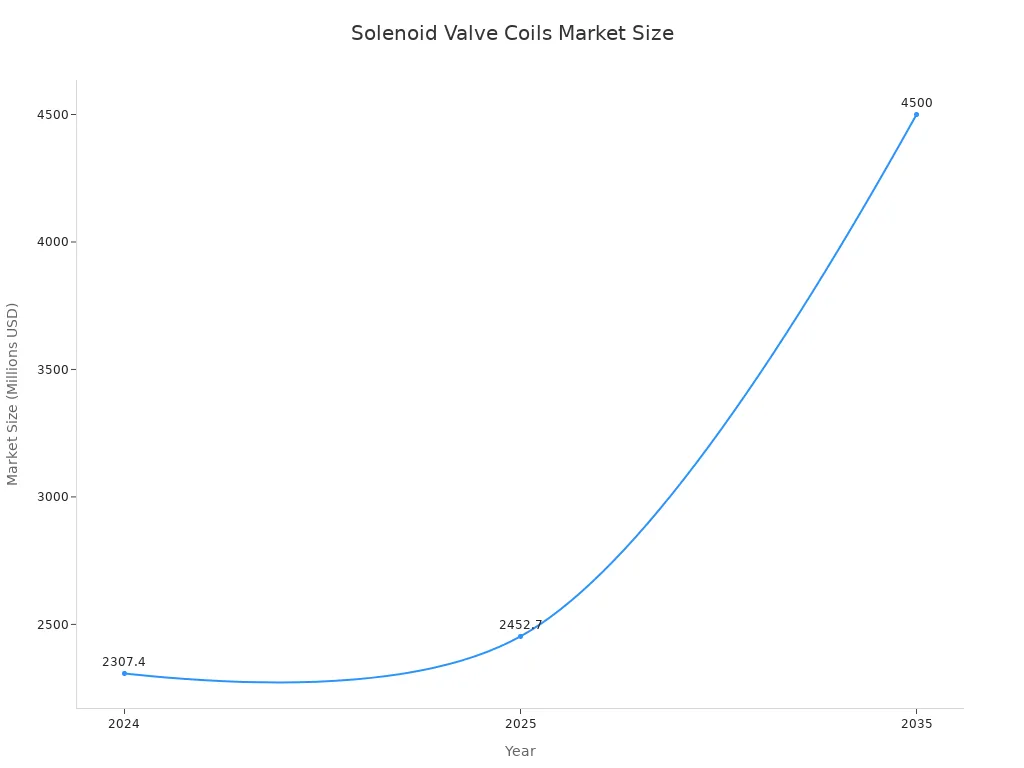
Key Takeaways
- Match the solenoid coil’s voltage to your power supply. Using the wrong voltage can cause the coil to fail or burn out.
- Choose a coil with the right duty cycle. This means picking a coil that can handle how often it needs to turn on and off without overheating.
- Select an insulation class that fits your environment. This protects the coil from high temperatures and helps it last longer.
What is a Solenoid Valve Coil?
Function of a Solenoid Valve Coil
A solenoid converts electrical energy into a linear mechanical force. It functions as an electromagnetic coil. The flow of current generates magnetism, which physically moves an armature. This movable armature, often a rod or metallic arm, operates valves. In a plunger solenoid, an electrical current passing through the coil creates a magnetic field. This field attracts a movable iron rod into the coil chamber. This movement then controls mechanical devices like valve seats. When power is applied, an electric current travels through the solenoid’s wire coil, generating a magnetic field. This magnetic field exerts a force on the armature, causing it to move. This motion is typically back and forth in a linear solenoid. The armature’s movement performs tasks such as opening or closing valves. Upon cessation of the electric current, a spring returns the armature to its initial position. This prepares the solenoid for its next operational cycle.
Basic Components of a Solenoid Valve Coil
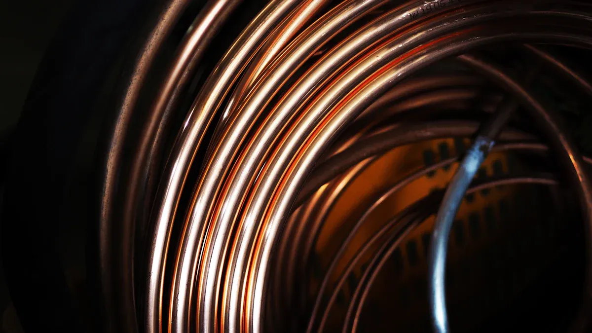
A Solenoid Valve Coil is engineered to transform electrical energy into lateral motion. This is achieved by winding copper wire around a hollow bobbin or tube. When an electric current traverses this coil, it produces a magnetic field. The core or plunger is the magnetic element that moves when the solenoid is energized. It is positioned coaxially with the solenoid. Its movement makes or breaks the seals that regulate fluid flow. When the coil is de-energized, springs maintain the core in its normal position. The solenoid coil itself consists of numerous turns of copper wire encircling the core tube. This induces the core’s movement. An iron frame often encases the coil, providing a path of low magnetic resistance. Placing the solenoid valve coil over a ferromagnetic core, typically made of magnetic 430F stainless steel, causes the magnetic field to draw the plunger further into the coil. This creates an opening that controls various types of solenoid valves.
Solenoid Valve Coil Voltages
AC Solenoid Valve Coils
Alternating Current (AC) solenoid valve coils operate on power that periodically reverses direction. Common voltage ratings include 120V and 220V. Coils operating above 24 volts are typically utilized in factories and heavy machinery. Industrial applications often use AC solenoid valve coils with voltage ranges of 24-120V AC/DC and 100-240V AC/DC. AC coils are suitable for applications requiring high power and fast response times.
DC Solenoid Valve Coils
Direct Current (DC) solenoid valve coils operate on power that flows in one direction. Standard DC voltages for solenoid valve coils include 6VDC, 12VDC, and 24VDC. DC solenoids are commonly used in low-power applications, such as locks, relays, and small actuators. For instance, the Wattmizer is a miniature 12VDC solenoid valve designed for compact areas requiring low power draw. DC coils are ideal for battery-powered systems or applications where power consumption is a critical factor.
Selecting the Correct Solenoid Valve Coil Voltage
Selecting the correct voltage for a solenoid valve coil is crucial for optimal performance and longevity. Power availability significantly influences this selection. The valve must suit the available AC or DC power source. AC valves cannot convert to DC, or vice versa, simply by changing the coil. Solenoid valves operate within a nominal voltage range of plus or minus 10%. Undervoltage leads to operational failures, excessive noise, chattering, and a reduced lifespan. Overvoltage results in overheating, premature solenoid failure, and a shortened lifespan. Key factors influencing selection include AC vs. DC voltage compatibility and considering lower wattage coils for reduced energy consumption.
Solenoid Valve Coil Temperature Ratings and Insulation Classes
Understanding Insulation Class
Insulation class defines the maximum temperature an electrical component’s insulation material can withstand continuously without degrading. This rating is crucial for the longevity and safe operation of electrical devices. For solenoid valve coils, the insulation class indicates the highest temperature the coil winding can reach during operation. This temperature includes both the ambient temperature and the temperature rise due to the coil’s own electrical resistance.
| Aspect | Description |
|---|---|
| Definition | Insulation class specifies the maximum temperature an electrical component’s insulation material can endure continuously without thermal degradation. |
| Purpose | It ensures the longevity and safe operation of electrical devices by preventing insulation breakdown. |
| Application | For solenoid valve coils, it indicates the highest permissible temperature for the coil winding during operation. |
| Factors | This temperature accounts for both the surrounding ambient temperature and the heat generated by the coil’s electrical resistance. |
Common Solenoid Valve Coil Insulation Classes
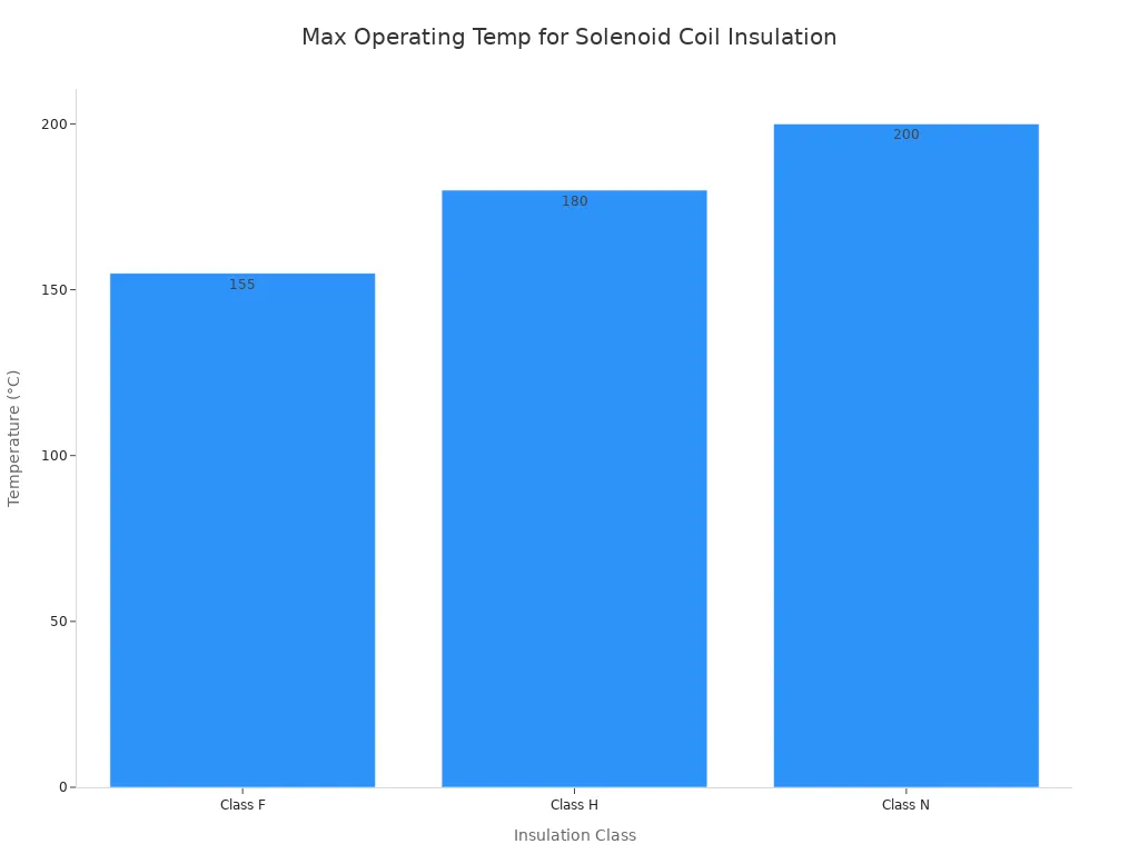
Different insulation classes exist, each designed for specific temperature tolerances. These classes are standardized to help manufacturers and users select appropriate components for various operating environments. Common insulation classes for solenoid valve coils include Class F, Class H, and Class N. Each class specifies a maximum operating temperature.
| Insulation Class | Maximum Operating Temperature |
|---|---|
| Class F | 155°C |
| Class H | 180°C |
| Class N | 200°C |
Impact of Temperature on Solenoid Valve Coil Life
Temperature significantly affects the lifespan and reliability of a coil. High operating temperatures accelerate the degradation of insulation materials. This degradation is the most common phenomenon affecting the service life of solenoid valves.
- Insulation degradation of the electromagnetic coil is the most common phenomenon affecting the service life of solenoid valves.
- This failure mode leads to thermal and compressive stress concentration.
- It results in the aging of insulation materials, inter-turn short circuits, and can ultimately cause coil burnout. Excessive heat causes the insulation to become brittle and crack. This compromises the electrical integrity of the coil. Eventually, this leads to short circuits and complete coil failure. Maintaining the coil within its specified temperature limits is essential for long-term performance.
Choosing the Right Insulation Class for Solenoid Valve Coils
Selecting the correct insulation class ensures the coil operates reliably in its intended environment. Engineers must consider the ambient conditions within control panels. The coil insulation classes and their temperature rise limits must correspond with these ambient conditions.
When selecting a solenoid valve, after verifying inrush and holding power against panel capacity, confirm the insulation class is appropriate for the ambient temperature inside control cabinets. For high-temperature applications, it is recommended to use Class H insulated coils. These coils offer heat resistance up to 180°C. Choosing an insulation class that exceeds the expected operating temperature provides an additional safety margin. This practice enhances the coil’s durability and prevents premature failure.
Solenoid Valve Coil Duty Rating Explained
What is Solenoid Valve Coil Duty Cycle?
The duty cycle of a solenoid coil represents the proportion of time a solenoid remains energized. Engineers define it as the ratio, expressed as a percentage, of the ON TIME (when the valve is energized) to the total Cycle Time (ON TIME + OFF TIME). The formula for this calculation is: Duty Cycle = On Time / (On Time + Off Time). For example, if a solenoid is energized for 15 seconds and then off for 45 seconds, the total cycle is 60 seconds, resulting in a 25% duty cycle. A continuous energization implies a 100% duty cycle.
Continuous Duty Solenoid Valve Coils
Continuous duty solenoid valve coils are designed for applications requiring constant energization. They handle rapid and frequent switching, often responding within milliseconds. These coils feature low power consumption and minimal heat generation. This makes them suitable for automated processes needing continuous operation. Common applications include electronic door locks, automotive transmission control, and fluid control valves in medical equipment.
Intermittent Duty Solenoid Valve Coils
Intermittent duty solenoid valve coils operate for shorter periods, requiring rest intervals between cycles. These coils are not designed for continuous energization. They typically handle higher power for brief durations. This design prevents overheating and extends their operational life in applications with periodic activation.
Calculating Solenoid Valve Coil Duty Cycle
To calculate the duty cycle, one uses the formula: Duty Cycle = On Time / (On Time + Off Time). This ratio is typically expressed as a percentage. Engineers can monitor the coil current or voltage during operation to determine the ‘On Time’ and ‘Off Time’. Dividing the total ‘On Time’ by the sum of ‘On Time’ and ‘Off Time’ provides the average duty cycle for the application.
Importance of Matching Solenoid Valve Coil Duty Rating
Matching the solenoid valve coil’s duty rating to the application’s operational requirements is critical. Not aligning the valve’s design with the operation cycle can significantly shorten its lifespan. High cycle frequency can wear out a valve faster if it is not rated for such operation. A valve mismatched to the power supply can fail to actuate. Incorrect voltage can lead to overheating, reduce equipment longevity, and cause malfunctions. Using the wrong coil type, such as replacing a 24V AC coil with a 24V DC coil, can damage the entire system due to fundamental design differences.
Power Levels for Solenoid Valve Coils
Watts vs. VA in Solenoid Valve Coils
Watts represent the ‘real power’ that performs work or generates heat. This indicates the rate at which energy consumes. VA (Volt-Amperes) measures ‘apparent power.’ Engineers calculate it as the product of RMS voltage and RMS current. It is crucial for sizing wires and fuses. The relationship between Watts and VA is defined by the power factor. This is the cosine of the phase angle between voltage and current. Watts equals VA multiplied by the power factor. For reactive loads like AC solenoid valves, the phase angle can be significant. This leads to a large difference between VA and Watts. VA accounts for the total current drawn. Watts reflect the actual power dissipated. In industrial settings, VA is critical for calculating power distribution, cable sizing, and managing reactive power. AC solenoid valves can draw substantial reactive power, particularly during inrush. DC coils are nearly purely resistive. This makes Watts and VA essentially equivalent for DC applications.
Inrush and Holding Current for Solenoid Valve Coils
AC solenoid coils experience an inrush current. This is the maximum current flow that occurs when the solenoid is initially energized. It typically lasts a very short duration, around 20 to 50 milliseconds. This happens when the armature is de-energized, reducing the coil’s inductance. Once the armature is fully seated, the inductance increases. This limits the current to its lower ‘holding’ value. The power source must supply this initial inrush current. For DC coils, inductance primarily causes a short delay in current response. It does not create distinct inrush and holding current values in the same way as AC coils. Inductance does not affect the steady-state current flow for DC.
Effects of Incorrect Power on Solenoid Valve Coils
Incorrect power levels can severely impact solenoid valve performance and longevity. Under-power conditions, specifically insufficient internal power, can lead to residual magnetic force. This causes valves with wet armatures to stick open when the coil is de-energized. There is not enough power to move the coil back to its closed position. Over-power conditions, such as extended energization or voltage spikes, cause coil burnout. Solenoid coils generate heat when energized. Excessive heat leads to complete valve failure. Incorrect voltage or electrical power supply issues also prevent proper functioning. This results in intermittent operation or complete failure.
Why Do Solenoid Valve Coils Burn Out?
Common Causes of Solenoid Valve Coil Failure
Several factors contribute to the failure of coils, often leading to burnout. Understanding these causes helps prevent premature equipment failure and ensures system reliability.
- Overvoltage: Supplying a voltage higher than the coil’s rated voltage causes excessive current flow. This leads to overheating and eventual burnout.
- Undervoltage: Supplying a voltage lower than the rated voltage prevents the solenoid from fully engaging. It causes the coil to draw inrush current continuously, which also leads to overheating.
- High Inrush Current: AC coils are particularly susceptible to burnout due to high inrush current. This current can be up to five times higher than the normal operating current.
- Rapid Cycling: Frequent activation of coils can lead to overheating, especially in AC coils. The heat cannot dissipate quickly enough between cycles.
- Electrical Transients: High voltage transients, generated by switching large inductive devices, damage the insulation of coils.
- Contaminants and Environmental Factors: Dirt, oil, and other contaminants cause mechanical issues. These issues lead to excessive current draw. Extreme temperatures (high or low) and high humidity affect performance and damage insulation or cause corrosion.
- Dead End Service: A coil remaining energized for long periods without fluid flow may burn out. Fluid circulation helps dissipate electrical heat.
- Atmospheric Moisture: High humidity combined with changing ambient temperature causes corrosion on metal parts. This leads to armature drag or spool sticking. It also deteriorates standard coils, causing shorts.
- Excessive Flow Through Valve: Pressure drop from fluid flow through a direct-acting valve creates an axial force unbalance. This potentially overloads the valve beyond its manufacturer’s flow rating, especially with high viscosity or specific gravity fluids.
Overvoltage and Undervoltage Issues
Incorrect voltage supply significantly impacts coil longevity and performance. Both overvoltage and undervoltage conditions promote coil damage, humming, and eventual burnout.
- Undervoltage Effects:
- A valve may respond slowly or fail to operate completely.
- The plunger might not move, causing the coil to overheat and potentially burn out.
- Increased operational noise may be observed.
- The coil heats up more than it should.
- Prolonged overheating from undervoltage leads to coil burnout, necessitating replacement.
- Overvoltage Effects:
- Excessive heat leads to coil failure.
- Increased heat degrades coil components.
- The overall valve lifespan is reduced.
- While brief voltage spikes (up to 50-100% for about one second) might be acceptable, prolonged exposure quickly results in coil failure.
Electrical failures often stem from incorrect voltage supply, causing overcurrent or undervoltage issues. Coil burnout occurs when insulation breaks down due to this excessive heat.
Overheating and Environmental Factors
Environmental conditions play a critical role in coil degradation and failure. High operating temperatures accelerate the degradation of seals and coils. Freezing temperatures can cause fluids to solidify, jamming the valve or damaging seals.
- Extreme Temperatures: High temperatures reduce the coil’s ability to dissipate heat. Temperature cycling can crack insulation. A 10°C increase typically halves coil life expectancy.
- Humidity and Moisture: These factors lead to moisture penetration, creating electrical leakage paths. They also accelerate corrosion of copper windings. If coils are not adequately sealed, moisture ingress causes corrosion and electrical faults.
- Vibration: Continuous vibration causes wire fatigue and loosens connections. It creates intermittent contacts that generate heat and arcing. This can loosen fittings and damage internal valve components over time.
- Chemical Exposure: Aggressive chemicals attack coil insulation, wire coatings, and housing materials. This leads to long-term degradation.
The chart below illustrates the estimated percentage reduction in coil life due to various environmental factors.

| Environmental Factor | Impact on Coil Life | Mitigation Strategy |
|---|---|---|
| High temperature (>60°C) | 50% reduction per 10°C | Improved ventilation, heat shields |
| High humidity (>85% RH) | 30-40% reduction | Better sealing, drainage |
| Continuous vibration | 40-60% reduction | Isolation mounts, flexible connections |
| Chemical exposure | Variable, severe | Chemical-resistant enclosures |
Mechanical Stress on Solenoid Valve Coils
Mechanical stress also contributes to coil failure. Physical impact or damage during installation or operation can compromise the coil’s integrity. Misalignment of the coil or other valve components places undue strain on the system. This can lead to increased friction and wear. If the plunger sticks or binds due to contaminants or wear, the coil must exert more force. This causes it to work harder and generate excessive heat. Improper mounting can also lead to strain on electrical connections or the coil housing itself, potentially causing internal damage or short circuits over time.
Why Does a Solenoid Valve Coil Get Burnt When Removed from a Valve?
Role of the Plunger in Solenoid Valve Coil Cooling
The plunger plays a critical role in the thermal management of a solenoid coil. When the plunger is fully inserted into the coil, it completes the magnetic circuit. For AC coils, this significantly increases the coil’s inductance. Higher inductance limits the current flowing through the coil. A lower current means less heat generation. The plunger also acts as a heat sink. It absorbs heat from the coil windings and dissipates it into the surrounding valve body. This conductive heat transfer helps maintain the coil within its safe operating temperature range. Without the plunger, the coil lacks this essential cooling mechanism.
Heat Dissipation Without the Plunger
When a solenoid coil operates without its plunger, it quickly overheats and burns out. For AC coils, removing the plunger drastically reduces the coil’s inductance. This allows a much higher current to flow through the windings. This excessive current generates a significant amount of heat very rapidly. Simultaneously, the primary path for heat dissipation, the plunger acting as a heat sink, is absent. The coil cannot effectively shed the heat it produces. This rapid temperature rise quickly degrades the insulation material. The coil then experiences an internal short circuit, leading to burnout. Therefore, engineers must ensure the plunger is always in place when energizing a Solenoid Valve Coil.
Solenoid Valve Coil Sizing and Compatibility
Matching Solenoid Valve Coil to Valve Body
Properly matching a coil to its valve body ensures correct function and long-term reliability. Engineers consider several critical parameters. Voltage options are important. Solenoid valves come in various voltages, such as 12V DC, 24V DC, 24V AC, 110V AC, and 220V AC. The control system dictates this selection. Low-voltage coils suit portable systems. Standard AC is common for industrial use. The coil insulation class is also vital, especially in high-temperature environments. Power consumption is critical for energy-sensitive applications. Energy-saving coils can reduce wattage after initial activation for continuous operation.
Voltage stability is another key factor. Operating outside the specified voltage range causes damage. High voltage leads to overheating or burnout. Low voltage causes inconsistent operation or chattering. Surge protection devices help maintain consistent electrical input. They protect the coil from transients, particularly in industrial settings with frequent motor or relay switching. Ambient temperature also affects performance. Extreme temperatures impact seal flexibility, coil resistance, and mechanical clearances. High temperatures soften seals and overheat coils. Freezing conditions cause cracking or blockage. Manufacturers provide temperature ratings for solenoid valves. For demanding environments, consider models with thermoplastic encapsulated coils, PTFE seals, or IP-rated enclosures. These resist moisture and dust. Valve body material and seal materials are also important. Materials like brass, stainless steel, or engineered plastics have specific strengths. Seal materials such as NBR, EPDM, or Viton must be compatible with the system fluid and operating temperature. Incorrect material choice leads to hardening, swelling, or cracking.
Physical Dimensions and Connectors
Physical dimensions and connector types are crucial for installation and electrical connection. Standardized connectors ensure compatibility across different manufacturers. These connectors vary in housing shape, pin configuration, and electrical ratings.
| Connector Type | Housing Shape | Pin Spacing (mm) | Pins | Rated Voltage (V) | Rated Current (A) | Common Thread Types |
|---|---|---|---|---|---|---|
| Form A | Square | 18 | 2 or 3 (incl. ground) | Up to 250 | Up to 16 | PG 9, PG 11, M16, NPT 1/2 in |
| Form B | Rectangular | 10 or 11 | 1 flat-blade & 2 U-shaped (10mm) or 3 flat-blade (11mm) | Up to 125 | Up to 10 | PG 9, NPT 1/2 in |
| Form C | Square | 8 or 9.4 | 2 or 3 (incl. ground) | Up to 125 | Up to 6 | PG 7 |
| M12 | Compact | N/A | N/A | N/A | N/A | N/A |
| DIN 43650 | Standard | N/A | N/A | N/A | N/A | N/A |
| Eurofast | Quick-connect | N/A | N/A | N/A | N/A | N/A |
Form A, B, and C connectors are common. They offer different pin spacings and current capacities. M12, DIN 43650, and Eurofast connectors provide compact or quick-connect solutions. Selecting the correct physical size and connector type ensures a secure fit and reliable electrical contact.
Solenoid Valve Coil IP Protection Levels
Understanding IP Ratings for Solenoid Valve Coils
IP (Ingress Protection) ratings classify the degree of protection electrical enclosures provide against solids and liquids. These ratings are crucial for ensuring the safe and reliable operation of electrical components, including solenoid valve coils, in various environments. An IP rating consists of two digits. The first digit indicates protection against solid objects, and the second digit indicates protection against liquids.
| Digit | Protection Level | Description |
|---|---|---|
| First Digit (Solid Object Protection) | ||
| 0 | No special protection | No protection against solid objects. |
| 1 | Large solid objects (>50mm) | Protected against accidental contact with large objects like a hand. |
| 2 | Medium solid objects (>12mm) | Protected against objects like a finger. |
| 3 | Small solid objects (>2.5mm) | Protected against tools, wires, or similar objects. |
| 4 | Very small solid objects (>1mm) | Protected against small insects or thin wires. |
| 5 | Dust-protected | Dust ingress is not entirely prevented but will not interfere with operation. |
| 6 | Dust-tight | Completely protected against dust ingress. |
| Second Digit (Liquid Protection) | ||
| 0 | No protection | No protection against liquids. |
| 1 | Vertically falling drops | Protected against condensation or vertically dripping water. |
| 2 | Tilted vertically falling drops | Protected against vertically dripping water when tilted up to 15 degrees. |
| 3 | Spraying water | Protected against spraying water at angles up to 60 degrees from vertical. |
| 4 | Splashing water | Protected against splashing water from any direction. |
| 5 | Water jets | Protected against water jets from any direction. |
| 6 | Powerful water jets/heavy seas | Protected against powerful water jets and heavy seas. |
| 7 | Temporary immersion | Can be temporarily immersed in water up to 1m deep for a limited time. |
| 8 | Continuous immersion | Can be continuously immersed in water under specified conditions. |
| 9 | High-pressure, high-temperature jets | Protected against high-pressure, high-temperature water jets (e.g., industrial cleaning). |
Selecting for Environmental Conditions
Choosing the correct IP rating is vital for the longevity and safety of a solenoid valve. Manufacturers employ several methods to enhance ingress protection. Tubular frames offer better shielding than box frames. Flexible neoprene boots seal gaps, preventing moisture. Specialized watertight connectors are essential for IP63 or higher ratings. Plastic overmolding can seal the coil, often achieving IP65. Potting fills air gaps, providing IP65 protection.
| IP Rating | Protection Against Solids | Protection Against Liquids | Suitable Environmental Conditions |
|---|---|---|---|
| IP54 | Dust ingress | Splashing water | General environments with some dust and splashing water |
| IP64 | Dust-tight | Splashing water from all directions | Environments requiring dust-tightness and protection from splashing water |
| IP65 | Dust-tight | Water jets | Outdoor applications exposed to rain and dust |
| IP67 | Dust-tight | Immersion up to 1 meter | Environments where temporary submersion is possible |
| IP68 | Dust-tight | Continuous immersion beyond 1 meter | Underwater applications or areas prone to flooding |
Most solenoid valves in the European community typically have an IP65 rating. However, some Asian, high-temperature, and cryogenic solenoid valves might have an IP54 rating or less. These often feature flying lead wires. When selecting a valve, especially for applications involving water or dust ingress, IP ratings are crucial. Consider the worst-case scenario. Electricity can cause severe injury, particularly with water or moisture. It can also ignite dusty environments. Factors like potential water spillage, leaks, maintenance, and cleaning require careful consideration.
Tips for Selecting the Right Solenoid Valve Coil
Selecting the correct Solenoid Valve Coil is crucial for system reliability and longevity. Engineers must consider several key specifications.
Voltage Selection Checklist
When choosing a coil, match its voltage and frequency to the available power supply. For AC coils, consider VA ratings. For DC coils, consider W ratings. Ensure the power source delivers the necessary inrush and holding current. Provide adequate ventilation for the coil. If the coil becomes too hot to touch, re-check the duty cycle, voltage at the terminals, and ambient conditions. Always ensure compatibility with the power supply, whether AC or DC. Lower wattage coils reduce energy consumption.
Duty Cycle Considerations
Evaluate the thermal characteristics of coils in relation to the application’s environment and duty cycle. This ensures reliable performance and reduces burnout risk. Select coils that operate efficiently within their specified duty cycle. This is especially important where weight and power efficiency are critical. Consider how often the coil needs to turn on and off. Some coils draw more power when running continuously. Others suit intermittent operation. Overheating from excessive duty cycles often causes electrical issues and premature failure. Optimize timer settings by adjusting pulse duration and interval for effective operation without over-cycling. Ensure valves fire one at a time to reduce strain.
Insulation Class Best Practices
Insulation class defines the maximum temperature a coil’s insulation can withstand. Class F tolerates temperatures above 155°C. Class H protects at operating temperatures over 180°C. Class N handles thermal stability exceeding 200°C. Key considerations include voltage, coil resistance, response time, and duty cycle. Environmental factors like temperature range, moisture exposure, and chemical resistance also matter. Materials with high electrical conductivity, like copper, minimize power loss. High heat resistance prevents thermal damage. Good mechanical strength protects against vibrations. Chemical-resistant coatings prevent corrosion in harsh environments.
Environmental Protection Factors
Consider the operating environment when selecting a coil. Factors like temperature, humidity, and potential chemical exposure directly impact coil life. Choose coils with appropriate IP ratings for protection against dust and liquids. Ensure the coil materials and construction withstand the specific environmental challenges of the application.
This guide explored critical solenoid valve coil specifications: voltage, duty cycle, insulation class, and IP ratings. Correct coil selection directly impacts system reliability and longevity. Engineers must carefully match these specifications to application requirements. This ensures optimal solenoid valve performance and prevents premature failure.
FAQ
What happens if a solenoid coil is under-powered?
Under-powering a solenoid coil causes operational failures. The valve may not fully actuate. This leads to excessive noise, chattering, and reduced lifespan.
Can one use an AC coil with a DC power supply?
No, one cannot use an AC coil with a DC power supply. AC and DC coils have fundamental design differences. Using the wrong power type damages the coil and the entire system.
Why is insulation class important for solenoid coils?
Insulation class indicates the maximum temperature a coil’s insulation can withstand. This rating ensures the coil operates safely and reliably. It prevents premature degradation and failure.
Post time: Dec-31-2025