

Selecting the correct solenoid valve coil specifications is crucial for optimal system performance. Voltage, duty cycle, and insulation class significantly influence the reliability and efficiency of solenoid valves. Incorrect voltage can lead to overheating and coil burnout, resulting in increased maintenance costs. Additionally, operating beyond the rated duty cycle may damage coil insulation, further impacting system reliability.
Key Takeaways
- Select the correct voltage rating to prevent overheating and ensure compatibility with your system.
- Understand the duty cycle to determine how long your solenoid valve can operate without risk of damage.
- Choose an appropriate insulation class to protect against heat and ensure reliable performance in various environments.
Solenoid Valve Coil Voltage Specifications

Common Voltage Ratings
When selecting solenoid valve coils, engineers often encounter various voltage ratings. Understanding these ratings is essential for ensuring compatibility with the intended application. The most common voltage ratings for solenoid valve coils in industrial applications include:
| Voltage Rating | Application Description |
|---|---|
| 6V | Used in small devices like home appliances, cars, and basic automation tools. |
| 12V | Common in automotive applications and small machinery. |
| 24V | Widely used in industrial automation and control systems. |
| 120V | Suitable for heavy machinery and factory environments. |
| 220V | Often found in large industrial applications and equipment. |
Engineers must consider regional electrical standards when selecting voltage ratings. Compliance with these standards ensures that the solenoid valve coil meets the specific needs of the application.
- Ensure that the solenoid valve meets relevant standards such as CE marking, RoHS compliance, or ISO 9001.
- Choosing certified components enhances credibility in project documentation.
AC vs. DC Voltage Considerations
The choice between AC and DC voltage significantly impacts solenoid valve coil performance. AC solenoid valves typically consume a high initial power surge to generate the magnetic force needed to open the valve quickly. After opening, the current required to maintain the valve’s position drops significantly, leading to lower power consumption during steady operation.
In contrast, DC solenoid valves draw a steady, constant current from the start. This results in slower valve opening and higher overall energy consumption since the current remains above the minimum needed to keep the valve open. The following table summarizes the main differences in performance between AC and DC solenoid valve coils:
| Performance Aspect | AC Solenoid Valve Coils | DC Solenoid Valve Coils |
|---|---|---|
| Energy Efficiency | Initial inrush current causes higher power consumption; power drops after valve opens | No inrush current; constant, lower overall energy consumption; better for battery-powered systems |
| Power Supply | Requires AC power supply (24V, 110V, 220V); common in industrial/domestic settings | Requires DC power supply (12V, 24V); often battery or DC source dependent |
| Application Suitability | Suitable for stable AC power environments; quick response; higher starting force; used in HVAC, irrigation, industrial machinery | Suitable for precision control, smooth operation; preferred in automotive, portable, battery-powered equipment |
| Cost Considerations | Generally less expensive due to AC power availability and simpler design | Higher upfront cost due to DC power supply and complex control circuits |
| Response Time | Faster response (8-5 μs); can handle higher pressures; suitable for high-speed cycling | Slower response (30-40 μs); better for low pressure; avoids overheating from peak currents |
| Operational Characteristics | Subject to initial peak currents causing potential overheating with frequent cycling | No initial peak currents, reducing risk of coil damage or spool seizure |
| Power Losses | Higher electrical losses proportional to AC frequency (e.g., more at 60 Hz than 50 Hz) | Lower electrical losses due to steady current |
Effects of Voltage Variations
Voltage fluctuations can have significant effects on solenoid valve coil operation and safety. Engineers must be aware of these potential issues to ensure reliable performance.
| Effect | Description |
|---|---|
| Overheating | Excessive current due to incorrect voltage can lead to overheating and insulation damage. |
| Incomplete plunger movement | Incorrect voltage can result in insufficient magnetic force, causing the plunger to not fully engage. |
| Safety hazards | Overheating and incomplete operation can pose significant safety risks in system operations. |
Engineers should consider the following points regarding voltage variations:
- Overvoltage increases current, generating heat and risking insulation damage.
- Undervoltage weakens the magnetic field, leading to incomplete plunger movement.
Manufacturers typically specify acceptable voltage variation ranges for solenoid valve coils. For example, dual frequency applications may allow a variation of +/- 10%, while AC single frequency applications may permit a variation of +10% / -15%.
Understanding these voltage specifications is crucial for optimizing solenoid valve coil performance and ensuring system reliability.
Solenoid Valve Coil Duty Cycle
Defining Duty Cycle
The duty cycle of a solenoid valve coil represents the ratio of ON TIME to total cycle time, expressed as a percentage. This measurement is crucial for understanding how long a coil can operate without overheating. The following table summarizes the definition and an example calculation of duty cycle:
| Duty Cycle Definition | Explanation |
|---|---|
| Duty Cycle | The ratio of ON TIME to total cycle time (ON TIME + OFF TIME), expressed as a percentage. |
| Example Calculation | If ON TIME is 15 seconds and OFF TIME is 45 seconds, the duty cycle is 25%. |
| Standard Rating | Most solenoid coils are rated at a standard 100% duty cycle for general applications. |
Understanding the duty cycle helps engineers select the appropriate solenoid valve coil for their specific applications, ensuring reliable performance.
Factors Influencing Duty Cycle
Several operational factors significantly influence the duty cycle of solenoid valve coils. These include:
- Heat Generation: Heat arises primarily from current flow through the coil, as indicated by the formula I²RT. High current levels can lead to overheating, which may compromise the coil’s integrity.
- Current Flow: Concerns about excessive current, such as 80 Amps through a 1 mm diameter copper wire, highlight the importance of adhering to safe limits. Exceeding these limits can adversely affect the duty cycle.
- Resistance Changes: The resistance of copper increases with temperature, impacting power dissipation and, consequently, the duty cycle.
- Ambient Temperature: High ambient temperatures hinder the coil’s ability to cool down, increasing the risk of insulation failure. As coil temperature rises, its electrical resistance increases, reducing magnetic force and potentially causing valve malfunction.
Managing Coil Temperature
Effective temperature management is essential for maintaining the performance and longevity of solenoid valve coils during continuous operation. Engineers can employ several strategies to manage coil temperature:
| Method | Description |
|---|---|
| Adaptive Duty Cycle Management | Adjusts the on/off cycles of the actuator based on operational needs and temperature feedback to minimize heat buildup. |
| Temperature Monitoring and Control Systems | Utilize sensors and feedback loops to adjust the actuator’s operation in real-time, preventing excessive heat generation. |
| Energy-Efficient Actuation Methods | Techniques like pulse-width modulation and low-power circuits reduce energy consumption and heat generation. |
| Thermal Insulation Techniques | Employ heat-resistant materials and strategic component placement to prevent heat transfer and protect sensitive parts. |
| Fluid-Based Cooling Systems | Use working fluids or separate cooling fluids to absorb and dissipate heat, maintaining optimal temperatures during operation. |
Ignoring ambient heat is a common cause of solenoid valve failure. Engineers must consider these methods to ensure that solenoid valve coils operate within safe temperature limits, thereby enhancing their reliability and lifespan.
Solenoid Valve Coil Insulation Class
Significance of Insulation Class
The insulation class plays a critical role in solenoid valve coil selection. It determines the thermal endurance of the insulation material, affecting the solenoid’s ability to operate reliably under various conditions. A suitable insulation class prevents breakdowns that could lead to short circuits and safety hazards. Engineers must prioritize insulation class to ensure long-term performance and reliability.
Overview of Insulation Classes
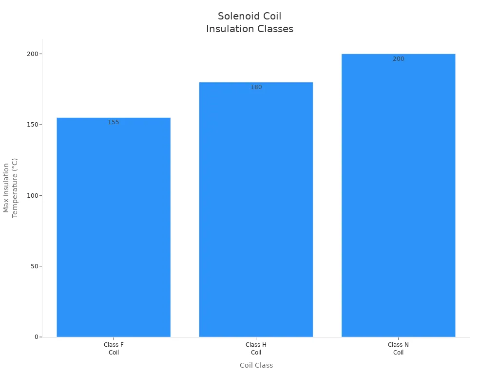
Several insulation classes exist for solenoid valve coils, each with specific maximum temperature ratings. The following table summarizes these classes:
| Coil Class | Maximum Insulation Temperature | Typical Applications |
|---|---|---|
| Class F Coil | 155°C | General pneumatic systems, compressed air, water |
| Class H Coil | 180°C | Steam systems, thermal oil pipelines |
| Class N Coil | 200°C | Superheated steam, extreme industrial environments |
Selecting Insulation Class
When selecting the appropriate insulation class for solenoid valve coils, engineers should consider several criteria:
- Ensure coil insulation classes align with ambient conditions inside control panels.
- Verify inrush and holding power against panel capacity.
- Confirm insulation class for ambient temperature inside control cabinets.
- Assign a duty cycle rating suitable for continuous service or intermittent pulsing.
- Consider environmental exposure for enclosure and coil protection requirements.
High-temperature environments require insulation classes that withstand overheating. Cold environments risk moisture freezing inside the valve, potentially damaging components. Manufacturers provide temperature ratings to guide selection based on operating conditions. By choosing coils with higher insulation classes, organizations can achieve greater system reliability and efficiency, leading to lower operational costs.
Engineers must carefully select solenoid valve coil voltage, duty cycle, and insulation class to ensure reliable operation. Key takeaways include:
- Choose voltage matching system control logic to avoid overheating.
- Understand duty cycle limits for continuous or intermittent use.
- Select insulation class that withstands operational heat for safety and longevity.
| Criteria | Recommendations |
|---|---|
| Voltage & Electrical Class | Confirm AC/DC type, frequency, and duty cycle rating. |
| Duty Cycle | Use continuous-duty coils for 100% operation; pulsed coils for intermittent use. |
| Surge Protection | Apply diodes or suppressors to protect control systems. |
| Environmental Protection | Select IP-rated coils for harsh conditions and verify hazardous area certifications if needed. |
Balancing cost and performance requires choosing coils that fit application needs without excess power. Proper specification improves system efficiency and reduces failures, as shown in industrial case studies. Engineers should verify coil ratings and environmental compatibility before installation to optimize solenoid valve performance.
FAQ
What is the ideal voltage for solenoid valve coils?
The ideal voltage matches the system’s specifications, typically ranging from 6V to 220V, depending on the application.
How does duty cycle affect solenoid valve performance?
Duty cycle determines how long a coil can operate without overheating. Higher duty cycles allow for continuous operation.
Why is insulation class important for solenoid valves?
Insulation class indicates the thermal endurance of the coil. A suitable class prevents breakdowns and ensures reliable operation.
Post time: Mar-30-2026