
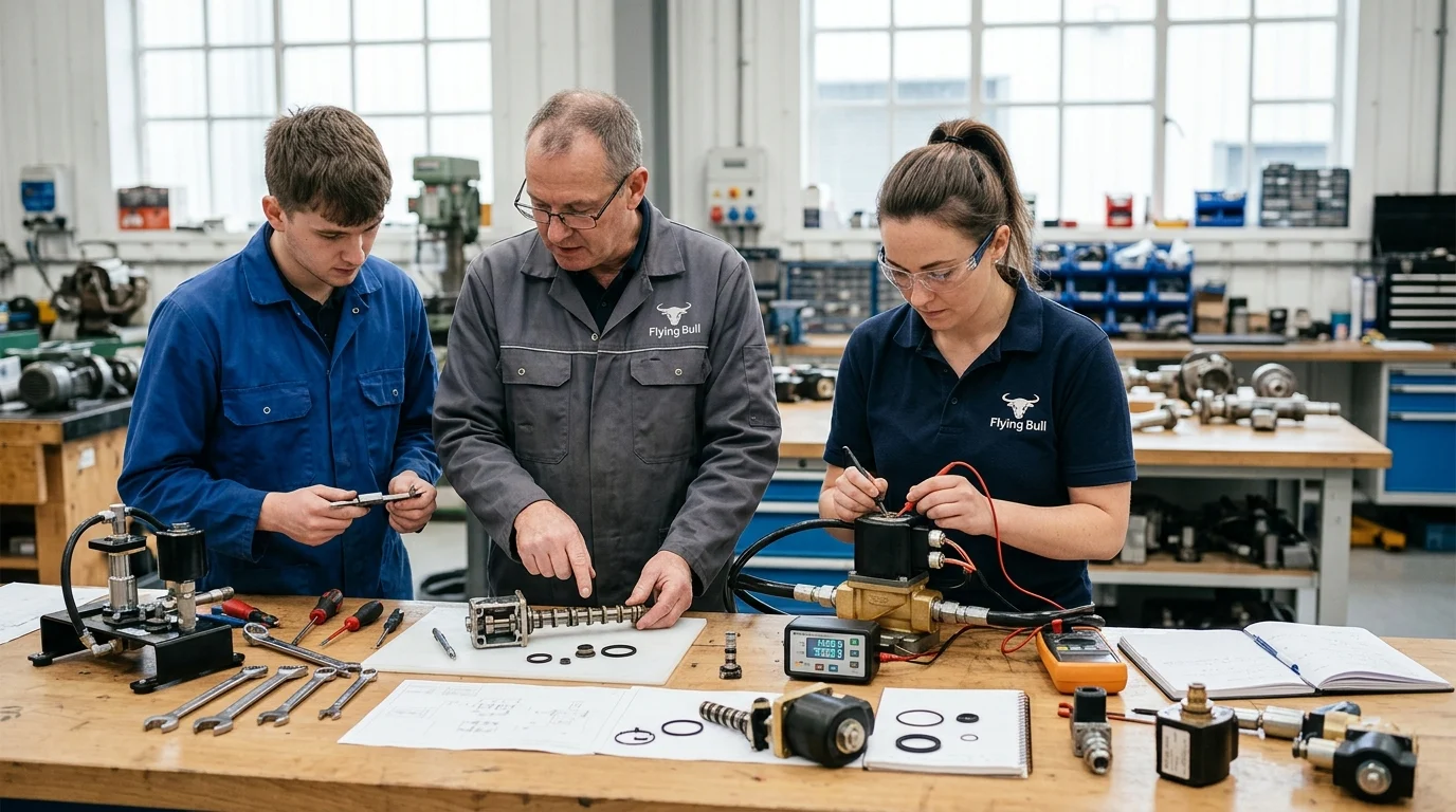
In heavy construction equipment, a small solenoid valve can decide whether an excavator keeps digging or sits idle at a costly standstill. Hydraulic control valves operate under punishing duty cycles, vibration, contamination, heat, and electrical transients—conditions that can turn minor tolerance drift into lost implement control or pressure instability. With downtime often exceeding $150 per hour in lost productivity, understanding failure mechanisms is not just a maintenance issue; it is an engineering priority. This article examines five recurring solenoid valve failure modes in earthmoving machinery and explains how Flying Bull’s engineering approach—covering machining precision, coil protection, materials control, and system-level safeguards—helps reduce field failures before they happen.
Common Failure Modes in Construction Machinery
Construction machinery hydraulic systems operate under relentless mechanical stress and extreme thermal fluctuations. At the heart of these directional and proportional control systems are solenoid valves, components whose reliability directly dictates the operational uptime of excavators, wheel loaders, and bulldozers. When these electro-hydraulic interfaces fail, operators face immediate loss of implement control or catastrophic system pressure drops. Flying Bull’s engineering team specializes in identifying and preventing these exact scenarios.
Industry estimates indicate the financial impact of such downtime can exceed $150 per hour in lost productivity, underscoring the necessity for robust component selection. Understanding how and why these valves fail in the field is the first step for the design team to engineer more resilient hydraulic circuits.
Solenoid Valve Failure Definitions
In heavy machinery, a solenoid valve failure is not strictly limited to catastrophic structural rupture or complete electrical open circuits. Engineering definitions classify failure as any deviation from specified performance tolerances that compromises hydraulic control. This includes sluggish spool actuation where response times exceed the standard 30 to 50 milliseconds, unacceptable internal leakage rates surpassing typical targets of 20 cc/min at 3,000 PSI, and intermittent electrical continuity under load. To fully address system vulnerabilities, engineers characterize these into five primary failure modes: spool binding, coil burnout, connector failure, seal extrusion, and internal spring fracture.
Duty Cycle, Vibration, Contamination, and Voltage Risks
The operational environment of earthmoving equipment introduces four severe risk factors that interact to cause these primary failure modes. First, duty cycles frequently exceed intended continuous ratings (100% ED), pushing coil temperatures beyond Class H insulation limits of 180°C and leading directly to thermal degradation. Second, high-frequency chassis vibration, evaluated per IEC 60068-2-6 standards, contributes to multiple mechanical and electrical faults; it induces work hardening in internal armature springs and degrades electrical connector pins. Third, fluid contamination remains the leading cause of hydraulic component mortality; particles can bridge spool clearances, leading to immediate mechanical lock. Finally, transient voltage spikes—often surging during alternator load dumps (tested per ISO 7637-2)—rapidly degrade coil windings and integrated transient voltage suppression (TVS) diodes.
Engineering Controls to Reduce Field Failure
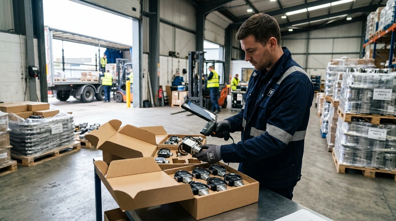
Mitigating the inherent risks of heavy-duty hydraulic applications requires a shift from reactive maintenance to proactive component engineering. Addressing the root causes of electro-hydraulic failures at the design and manufacturing stages is critical. By implementing proprietary metallurgical process controls, advanced coil potting techniques, and precise machining tolerances, Flying Bull’s engineering team dramatically extends the validated mean time between failures (MTBF) for solenoid valves deployed in aggressive environments. However, while component design prevents internal failures, maximizing lifespan also requires proper system filtration, voltage regulation, and regular maintenance intervals.
Contamination-Related Spool Sticking
Spool sticking induced by particulate contamination is the most pervasive mechanical failure mode in construction hydraulics. To combat this, precision machining is utilized to maintain tight radial clearances between the spool and the valve body, targeting industry benchmarks of 2 to 3 microns. While this micro-tolerance prevents larger particles from entering the dynamic shear zone, it inherently increases sensitivity to silt-sized contamination and demands premium filtration (such as ISO 4406 16/14/11 standards), which can increase overall system maintenance costs.
Furthermore, applying surface treatments elevates spool surface hardness to HRC 60-62. While nitrocarburizing is a common industry practice, Flying Bull utilizes proprietary thermal profiling to prevent the surface brittleness that often plagues standard treatments. This controlled hardening process effectively prevents abrasive silicates from scoring the spool lands, thereby eliminating the micro-burrs that typically cause mechanical binding.
Design and Quality Controls for Reliability
Beyond mechanical resilience against spool binding, preventing the remaining failure modes requires rigorous design and quality controls. The engineering team addresses each vulnerability with specific countermeasures, providing deep technical solutions rather than relying on standard off-the-shelf components:
- Coil Burnout: To prevent thermal failure, Flying Bull encapsulates coils using proprietary epoxy potting compounds with high thermal conductivity. While this ensures IP69K ingress protection and dissipates internal heat during 100% duty cycle operations, the operational trade-off is reduced field serviceability—a compromised coil cannot be repaired and must be replaced entirely.
- Connector Failure: To mitigate electrical disconnects caused by severe chassis vibration, Flying Bull goes beyond standard solutions by specifying overmolded Deutsch connectors with custom strain relief. This proprietary integration isolates terminal pins from high-frequency resonance, maintaining continuity under heavy mechanical stress.
- Seal Extrusion: Extreme pressure transients cause standard elastomers to extrude into valve clearances. This is countered by integrating custom-machined polyurethane or PTFE backup rings rated to withstand severe hydraulic spikes up to 5,000 PSI. However, installers must note that PTFE requires precise, temperature-controlled assembly to avoid cold flow deformation prior to operation.
- Spring Fracture: To prevent internal spring fracture from fatigue, Flying Bull’s quality control protocols mandate rigorous metallurgical validation. High-tensile alloy armature springs are tested against benchmarks of over 10 million cycles to validate field MTBF and ensure consistent mechanical return force.
Additionally, thermal shock testing—involving rapid transitions from -40°C to +120°C—is employed to guarantee that internal wire bonds and potting compounds do not fracture under extreme weather fluctuations.
| Failure Mode | Primary Root Cause | Engineered Control | Performance Metric |
|---|---|---|---|
| Coil Burnout | Voltage spikes & thermal overload | High-temp epoxy potting & TVS diodes | Class H (180°C) rating |
| Spool Binding | Particulate contamination | Proprietary nitrocarburized spools | HRC 60-62 hardness |
| Connector Failure | High-frequency chassis vibration | Overmolded Deutsch with strain relief | IEC 60068-2-6 compliant |
| Seal Extrusion | Extreme pressure transients | Polyurethane/PTFE backup rings | Rated to 5,000 PSI |
| Spring Fracture | High-frequency vibration/fatigue | High-tensile alloy springs | >10 million cycle life |
OEM and Distributor Sourcing Criteria
For original equipment manufacturers (OEMs) and heavy machinery aftermarket distributors, selecting a solenoid valve supplier extends beyond unit price comparisons.
Key Takeaways
- Treat solenoid valve failure as any loss of performance tolerance, including response times beyond 30–50 milliseconds or leakage above 20 cc/min at 3,000 PSI.
- Control hydraulic contamination aggressively because particles can bridge micron-level spool clearances and cause immediate sticking or erratic machine control.
- Specify coils and electrical protection for real construction-duty conditions, including 100% ED operation, high temperatures, and ISO 7637-2 voltage transients.
- Design and validate valves for vibration exposure because chassis vibration can damage connector pins and contribute to spring fatigue or fracture.
- Use precision-machined valves with 2–3 micron spool-to-body clearance targets, but support them with proper filtration, voltage regulation, and maintenance intervals.
Frequently Asked Questions
What is considered a solenoid valve failure in construction machinery?
Failure includes any performance deviation that compromises hydraulic control, such as slow spool response beyond 30–50 ms, internal leakage above about 20 cc/min at 3,000 PSI, intermittent electrical continuity, or complete coil or mechanical failure.
Why do solenoid valves fail more often in construction equipment?
Excavators, loaders, and bulldozers expose valves to high duty cycles, vibration, fluid contamination, thermal swings, and voltage spikes. These stresses can cause spool binding, coil burnout, connector damage, seal extrusion, and spring fracture.
How does contamination cause spool sticking?
Particles in hydraulic fluid can enter the tight clearance between the spool and valve body, bridging the gap and preventing smooth movement. This may lead to sluggish actuation, erratic control, or complete valve lock.
What role does duty cycle play in coil burnout?
When duty cycles exceed continuous ratings, coil temperature can rise beyond insulation limits, such as Class H’s 180°C threshold. Prolonged overheating degrades insulation, increases electrical resistance, and can eventually burn out the coil.
How does Flying Bull reduce solenoid valve failure risk?
Flying Bull uses engineering controls such as precision machining, metallurgical process control, advanced coil potting, vibration-aware design, and tight production tolerances to improve durability in harsh hydraulic applications.
Post time: Sep-09-2026