
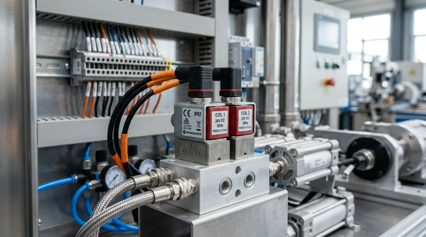
In European automation, reliability is increasingly measured not only by cycle life, but also by energy use, thermal load, and predictable behavior during outages. Dual-coil solenoid valve designs address these priorities by switching with short electrical pulses and holding position mechanically or magnetically without continuous current. That seemingly small change can reduce cabinet heat, protect coils from unnecessary stress, and support controlled recovery after power loss. This article explains how bistable dual-coil switching works, where it improves uptime, and what engineers must evaluate before specifying it—especially safety behavior, PLC control logic, pneumatic compatibility, and compliance expectations in modern European industrial systems.
Why Double Coil Switch Solenoid Valves Matter
Double coil switch solenoid valves—specifically referring to bistable or latching designs rather than redundant safety architectures—represent a foundational component in modern European automation. As industrial facilities across the continent prioritize stringent energy efficiency and robust fail-in-place safety mechanisms, the migration from traditional monostable valves to dual-coil configurations has accelerated. These components maintain their actuated state without continuous electrical power, fundamentally altering thermal management and power distribution strategies in high-density control cabinets.
How dual-coil switching works
The operational principle of dual-coil switching relies on two independent solenoids controlling a single directional spool or poppet. Energizing the first coil shifts the valve to its primary state, while a subsequent electrical pulse to the second coil returns it to the original position. Unlike single-coil variants that require continuous holding power, dual-coil valves only require a brief, application-dependent electrical pulse to change state. This pulse-driven actuation relies on mechanical detents or magnetic latching to hold the spool in place indefinitely until the next command is received, effectively eliminating the need for continuous holding current.
| Feature | Single Coil (Monostable) | Double Coil (Bistable) |
|---|---|---|
| Power Consumption | Continuous (application-dependent) | Pulse only (0W holding) |
| State on Power Loss | Returns to default position | Remains in last commanded position |
| Thermal Output | High (continuous heat generation) | Negligible |
| MTBF Impact | Baseline (seal wear dictates life) | Extends coil life (seal wear remains primary MTBF driver) |
Where they improve uptime
Mitigating thermal degradation—a primary cause of premature coil burnout in high-cycle automation networks—directly impacts system uptime. In high-vibration environments or continuous process industries, such as pharmaceutical manufacturing and automotive assembly, this thermal reduction extends coil lifespan compared to continuously energized models. However, it is important to note that mechanical fatigue and seal wear remain the primary drivers of overall Mean Time Between Failures (MTBF). Furthermore, in the event of a facility-wide power failure, dual-coil valves retain their last commanded position. This fail-in-place characteristic can prevent sudden, unintended pneumatic actuator movements, thereby protecting machinery and facilitating predictable recovery sequences.
Safety and Engineering Trade-offs: While advantageous for uptime, bistable behavior introduces specific engineering challenges that must be evaluated holistically. Retaining the last commanded state can create hazards in certain systems—such as maintaining uncontrolled clamping forces—where a fail-to-safe (spring-return) monostable valve is strictly required to protect human operators. Additionally, this actuation method introduces control-system complexity, requiring pulse-output PLC cards, specialized interlocking logic, and a higher initial capital expenditure (CapEx) compared to standard monostable setups.
Key Specifications and Compliance Factors

Specifying double coil solenoid valves for the European market requires strict adherence to regional electromechanical standards and environmental directives. Engineers must balance baseline pneumatic performance with rigorous compliance matrices to ensure seamless integration into existing Programmable Logic Controller (PLC) networks and pneumatic manifolds.
Electrical, pneumatic, and thermal requirements
European automation systems demand specific operational parameters to ensure reliability. Key requirements include:
- Electrical: Systems predominantly utilize 24V DC control voltages, though legacy infrastructure may still demand 110V or 230V AC configurations.
- Pneumatic: Valves must reliably operate within standard industrial pressures, typically rated between 1.5 and 8 bar. Pilot-operated designs require a minimum 1.5 bar operating pressure to shift the internal spool effectively. Flow capacity varies widely based on the manufacturer’s internal orifice geometry.
- Thermal: Because the coils do not generate continuous heat, these valves boast broader ambient operating temperature ranges, routinely specified from -10°C to +60°C.
- Environmental: Ingress protection ratings of IP65 or IP67 are typically required for harsh environments to shield the dual electrical connectors from dust and fluid ingress during aggressive washdown procedures.
CE, ATEX, IEC/EN, EMC, and safety standards
Regulatory compliance in Europe is legally obligatory for market access, beginning with the CE marking that indicates conformity with all relevant EU directives. For explosive atmospheres prevalent in chemical processing, ATEX certification assigns specific equipment categories (e.g., 2G or 3G) suitable for deployment in designated zones, utilizing protection concepts such as flameproof enclosures (Ex d) or encapsulated sealing (Ex m) for the electrical components. Electromagnetic Compatibility, governed by EMC Directive 2014/30/EU, is exceptionally critical for dual-coil units. Because they rely on brief electrical pulses to change state, the control circuitry must be highly immune to electromagnetic interference (EMI) that could otherwise induce false switching. Additionally, for functional safety applications, engineers seek components validated to EN IEC 61508 standards. This validation provides predictable failure rate data necessary for calculating the reliability of complete safety loops or subsystems targeting Safety Integrity Level (SIL) 2 or SIL 3, rather than certifying the standalone valve itself.
How to Source, Validate, and Deploy
Successfully integrating double coil switch solenoid valves into a production environment extends beyond baseline specifications. Procurement and engineering teams must execute systematic validation procedures and evaluate lifecycle costs to ensure the selected components deliver the promised reliability and supply chain resilience.
Validation steps that reduce commissioning risk
Commissioning dual-coil systems requires specific Factory Acceptance Testing (FAT) protocols tailored to bistable behavior and extends beyond standard monostable wiring procedures. Engineers must validate the minimum pulse width generated by the PLC; if the control system outputs a pulse shorter than the valve’s manufacturer-specified threshold, the spool may fail to shift completely, causing pneumatic blow-by or partial actuation. Leakage testing is another critical validation step, with acceptable pneumatic leak rates held to manufacturer-specific limits to prevent slow actuator drift during prolonged power-off states. Validation must also confirm that concurrent energization of both coils—a common programming error during PLC logic development—is prevented via strict electronic interlocking logic, as simultaneous power can cause thermal overload, excessive current draw, or mechanical deadlock. Furthermore, mechanical lifecycle testing should confirm the valves are rated for the application-dependent cycle count before requiring seal replacement.
Decision criteria for cost, availability, and reliability
When evaluating Total Cost of Ownership (TCO), decision-makers must weigh the initial capital expenditure against long-term operational savings.
Key Takeaways
- Specify bistable double coil valves when the application benefits from pulse-only actuation and 0W holding power.
- Use dual-coil technology to reduce cabinet heat and lower the risk of premature coil degradation in high-density automation panels.
- Confirm that fail-in-place behavior is acceptable, because a retained valve state may be unsafe where spring-return fail-safe action is required.
- Plan for PLC pulse-output capability, interlocking logic, and commissioning checks before migrating from monostable valve designs.
- Treat coil life improvement as one reliability gain, but continue managing seal wear and mechanical fatigue as major MTBF factors.
Frequently Asked Questions
What is a double coil switch solenoid valve?
It is typically a bistable or latching valve with two coils: one coil shifts the valve to one state, and the other shifts it back. It does not need continuous power to hold position.
How do dual-coil valves reduce energy consumption?
They use brief electrical pulses only during switching and consume 0W holding power once latched, unlike monostable valves that may require continuous current.
What happens to a double coil valve during power loss?
A bistable double coil valve usually remains in its last commanded position, supporting fail-in-place behavior and predictable restart sequences.
Are double coil solenoid valves always safer than single coil valves?
No. Fail-in-place behavior can be useful, but some applications require spring-return fail-safe operation to release pressure, unclamp parts, or protect operators.
Where are double coil valves most useful in automation?
They are valuable in high-density control cabinets, continuous process lines, pharmaceutical systems, automotive assembly, and applications where reduced heat and stable valve state improve uptime.
Post time: Jul-20-2026