
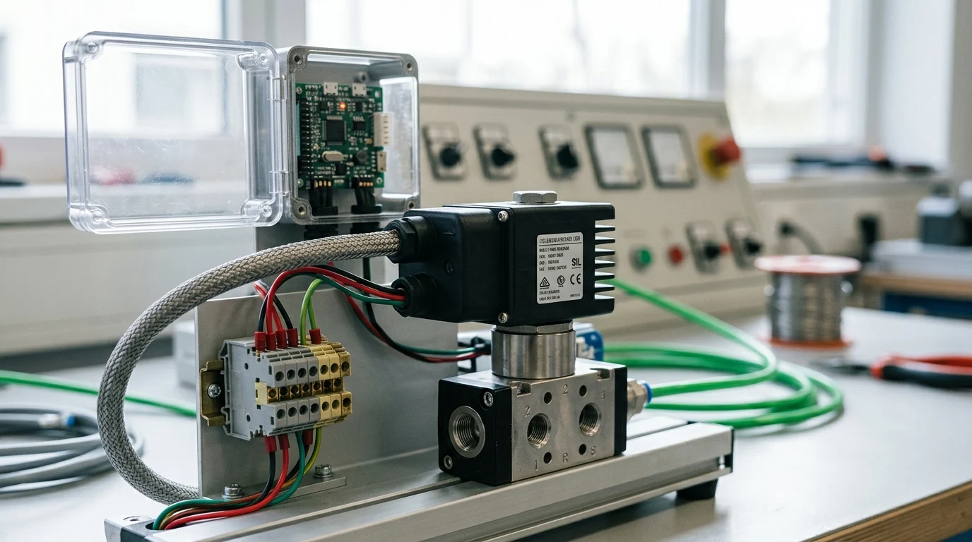
A solenoid coil may look like a simple on/off actuator, but in a safety-related valve system it becomes part of a much larger risk-control architecture. Engineers must prove not only that the coil energizes correctly, but that it fails predictably, releases fast enough, and is monitored with credible diagnostics. This article examines how functional safety concepts often associated with emerging references such as EN 17955:2025 should be grounded in IEC 61508 and IEC 61511. It explains SIL boundaries, de-energize-to-trip design, diagnostic coverage, hardware fault tolerance, and the practical trade-offs that determine whether a solenoid-driven final element can support a reliable safety instrumented function.
Functional Safety Basics for Solenoid Coils
The integration of solenoid coils into safety-related valve systems demands rigorous adherence to established functional safety standards, namely IEC 61508 and IEC 61511, to prevent catastrophic failures in process automation. While some industry discussions reference conceptual or hypothetical frameworks like EN 17955:2025, engineers must anchor all compliance and reliability evaluations for electromechanical actuators to verified IEC standards. These established standards connect general functional safety requirements with the specific operational realities of solenoid-driven fluid control, emphasizing systematic capability and lifecycle management.
Key EN 17955:2025 Definitions
When exploring the concepts often associated with the EN 17955:2025 label, it is vital to trace all failure metric definitions back to IEC 61508 principles. Safe Failure Fraction (SFF) and Diagnostic Coverage (DC) remain critical. It is important to clarify that a solenoid coil alone does not achieve a Safety Integrity Level (SIL) rating; rather, SIL claims apply to the safety instrumented function (SIF) or the final element subsystem (e.g., the combined valve, actuator, and coil). While a component might demonstrate an SFF of greater than 90% at a hardware fault tolerance (HFT) of zero, IEC 61508 architecture tables typically require an HFT of 1 (such as a 1oo2 architecture) or specific Route 2H proven-in-use justifications for SIL 3 final elements. Proper analysis requires establishing a clear boundary between the electrical coil assembly and the mechanical valve body, utilizing distinct Mean Time To Failure (MTTFd) calculations for the electromagnetic winding insulation versus the armature mechanism.
Safe Valve Actuation Principles
Safe valve actuation relies predominantly on the de-energize-to-trip principle. In these normally closed configurations, the removal of electrical power forces the valve to its safe state via a mechanical spring return. Established safety practices mandate strict verification of the spring force against potential armature stiction. Engineers must ensure that the residual magnetic field decays rapidly enough to meet process safety time constraints. Depending on the specific application, system designers might target a conditional de-energization response time—such as less than 50 milliseconds for certain high-speed emergency shutdown (ESD) valves. These application-specific targets require careful selection of coil inductance and suppression diode configurations to prevent delayed armature release.
Coil Diagnostics and Design Trade-Offs
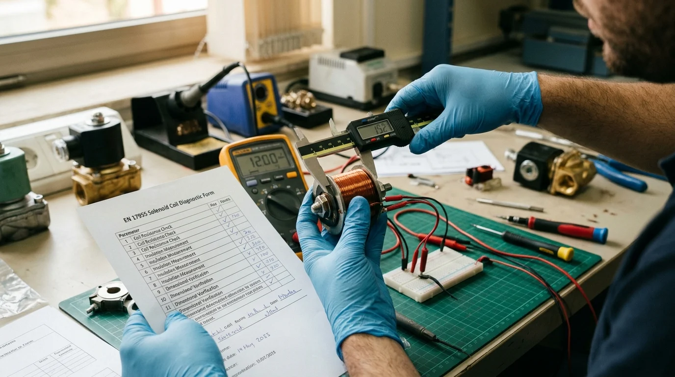
Balancing diagnostic capabilities with physical design constraints is a central challenge when engineering solenoid coils for safety-critical environments. Functional safety standards emphasize the need for continuous or periodic monitoring of the coil’s health without compromising its primary actuation function, while also accounting for potential common-cause failures (CCF) between the coil and its monitoring electronics.
Diagnostic Methods for Solenoid Coils
Modern safety systems employ various diagnostic techniques to detect latent faults before they lead to a dangerous failure on demand. It is crucial to sharply distinguish component-level diagnostics from subsystem-level diagnostics so that coil-fault coverage is not conflated with overall valve-assembly fault coverage. Impedance monitoring and current signature analysis are component-level methods highly effective at identifying partial short circuits in the coil windings or mechanical jamming of the armature. Conversely, subsystem-level methods like Partial Stroke Testing (PST) evaluate the entire final-element assembly, including the valve body and spring mechanism, rather than just the solenoid coil.
| Diagnostic Method | Scope | Fault Detected | Diagnostic Coverage (DC) | Implementation Complexity |
|---|---|---|---|---|
| Line Monitoring | Coil / Component | Open circuit, dead short | Low to Medium (60%) | Low |
| Current Signature Analysis | Coil / Component | Armature stiction, partial short | High (>90%) | High |
| Partial Stroke Testing (PST) | Valve Assembly / Subsystem | Valve sticking, spring failure | High (>90%) | Medium |
Response Time, Power, and Reliability Trade-Offs
The physical design of a solenoid coil dictates a strict trade-off between response time, power consumption, and long-term reliability. High-speed actuation requires substantial magnetic force, often necessitating high inrush currents that can exceed 20 watts. However, sustained high power consumption generates significant thermal stress, which can degrade the coil’s insulation lifespan and lower its MTTFd. To mitigate this, engineers frequently employ hit-and-hold circuits that apply a high initial current for rapid actuation, then reduce the holding power to a range of 2 to 5 watts. Safety standards require that thermal calculations account for maximum ambient operating conditions. While utilizing Class H insulation (rated for continuous operation at 180°C) provides a necessary thermal buffer, it is important to note that actual insulation lifespan and MTTFd depend heavily on manufacturer-specific construction, duty cycles, and thermal management, not solely on generic insulation class ratings.
Applying EN 17955:2025 in Engineering Practice
Translating the theoretical concepts associated with EN 17955:2025 into tangible engineering practice actually requires applying the systematic approaches defined in IEC 61508 and IEC 61511 for specification, risk assessment, and component validation. Engineers must effectively link component-level reliability data with system-level safety targets.
Specification and Risk Assessment Steps
The specification process begins with a rigorous risk assessment to determine the required SIL for the safety instrumented function (SIF). Once the target is established, engineers calculate the average Probability of Failure on Demand (PFDavg) for the entire control loop. The final element subsystem (solenoid coil, actuator, and valve assembly) typically accounts for the largest portion of the PFDavg budget; as an application-specific illustration, this can consume up to 50% of the allowable failure probability. IEC methodologies dictate how to calculate failure rates based on operational profiles. A critical variable in these calculations is the proof test interval. As a conditional example, continuous process plants might specify an 8,760-hour (one year) proof test interval. Such application-specific intervals require the solenoid coil to possess an exceptionally low dangerous undetected failure rate to maintain compliance over the continuous operational period.
Validation and Selection Guidance
Selecting a solenoid coil for a safety-related valve system demands comprehensive validation beyond basic electrical specifications. Engineers must procure components backed by detailed Failure Modes, Effects, and Diagnostic Analysis (FMEDA) reports compliant with IEC 61508. Environmental resilience is equally critical to validation.
Key Takeaways
- Use IEC 61508 and IEC 61511 as the compliance foundation when assessing solenoid coils in safety-related valve systems.
- Do not claim a standalone SIL rating for a solenoid coil; evaluate SIL at the SIF or final element subsystem level.
- For de-energize-to-trip valves, verify spring force against armature stiction and confirm that release time meets the process safety target.
- Keep coil diagnostics separate from valve subsystem diagnostics so diagnostic coverage is not overstated in safety calculations.
- Assess suppression diode and coil inductance choices because they can delay residual magnetic field decay and armature release.
- For SIL 3 final elements, expect architecture constraints such as HFT 1 or a justified proven-in-use Route 2H approach under IEC 61508.
Frequently Asked Questions
Can a solenoid coil have its own SIL rating?
No. SIL applies to the safety instrumented function or final element subsystem, such as the valve, actuator, and coil together. The coil contributes failure data and diagnostics, but it is not independently SIL-rated.
How should EN 17955:2025 be used in functional safety work?
Treat EN 17955:2025 references cautiously and anchor compliance claims to verified standards such as IEC 61508 and IEC 61511. Use established IEC terms for SFF, diagnostic coverage, hardware fault tolerance, and lifecycle management.
Why is de-energize-to-trip preferred for safety valves?
De-energize-to-trip designs move the valve to a safe state when power is removed, typically using a spring return. This reduces dependence on active electrical control during a shutdown demand.
What diagnostics are useful for solenoid coils?
Impedance monitoring and current signature analysis can detect winding shorts, degraded insulation, armature jamming, or abnormal actuation behavior. These are component-level diagnostics and should not be overstated as full valve diagnostic coverage.
What response-time issue can suppression diodes create?
A suppression diode can slow magnetic field decay after de-energization, delaying armature release. Engineers must select coil inductance and suppression methods that still meet the process safety time target.
Post time: Aug-12-2026