
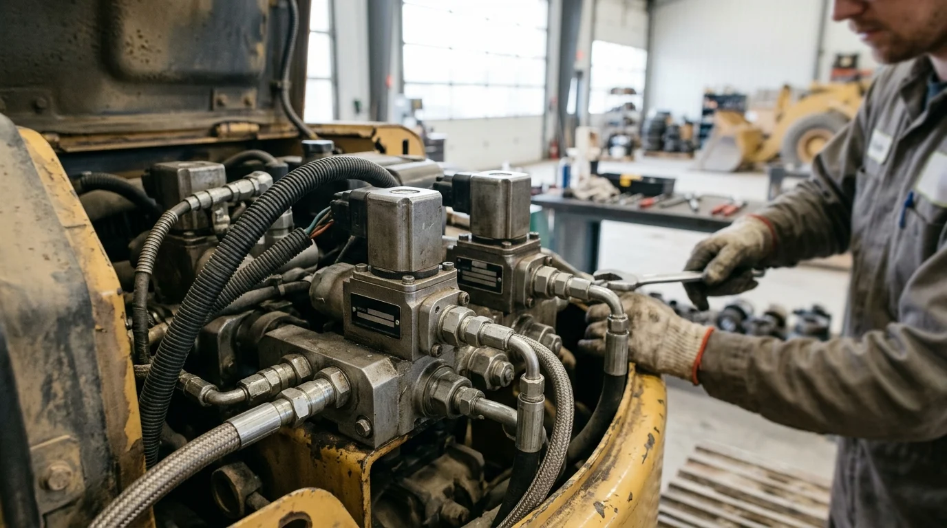
Modern construction machines increasingly depend on electronics to command hydraulic power with precision, speed, and reliability. In excavators, skid steers, and compact track loaders, the solenoid valve is the point where an ECU signal becomes boom movement, bucket curl, track propulsion, or attachment control. That makes specification decisions critical: pressure capability, flow rate, response time, leakage control, and heat generation all affect uptime in harsh North American jobsite conditions. This article examines the engineering requirements behind high-pressure mobile hydraulic valves, including 350 bar-class operation, 420 bar pressure spikes, flow ranges from pilot to implement circuits, and how Flying Bull’s valve architecture supports demanding construction machinery applications.
High-Pressure Hydraulic Solenoid Valve Basics
Hydraulic solenoid valves represent the critical interface between electronic control units and fluid power execution in modern mobile equipment. For North American construction machinery, these components must withstand severe duty cycles, extreme temperature variations, and mechanical vibration. Equipment downtime due to hydraulic failure carries significant financial penalties on construction sites, making component reliability a primary engineering objective. Flying Bull has positioned its manufacturing capabilities to meet these demands, offering a portfolio engineered for the operational profiles of heavy-duty earthmoving equipment, though engineers must carefully match valve specifications to specific machine duty cycles to avoid premature wear.
Definitions, Pressure Ratings, and Flow Capacity
To qualify as high-pressure components in mobile hydraulics, solenoid valves typically operate at continuous system pressures of 350 bar (5,075 PSI), with the structural integrity to withstand intermittent pressure spikes up to 420 bar (6,090 PSI). Flow capacity is equally critical for machine productivity; standard directional control valves manage flow rates ranging from 20 L/min for pilot circuits up to 150 L/min for main implement controls. Flying Bull utilizes computational fluid dynamics to optimize internal spool and gallery geometries, aiming to minimize pressure drops to less than 5 bar at maximum rated flow. This efficiency reduces parasitic heat generation in the hydraulic fluid, a practical consideration for the densely packaged engine compartments of North American machinery.
Key Construction Machinery Applications
Within the construction sector, these high-pressure valves manage functions such as boom hoist operations, bucket curl articulation, and track drive propulsion. In a standard 20-ton excavator, proportional solenoid valves dictate the metering of fluid to the main control valve, requiring step-response times under 30 milliseconds to ensure smooth operator feedback. Skid steer loaders and compact track loaders rely on rapid-acting on/off solenoid valves for auxiliary attachment controls and hydrostatic transmission modulation. Flying Bull’s high-pressure units utilize hardened steel spools and sleeves designed with target diametrical clearances often in the low single-digit micron range. This tolerance helps prevent excessive internal leakage while maintaining smooth actuation in high-vibration environments typical of trenching, grading, and demolition applications.
Technical and Compliance Evaluation
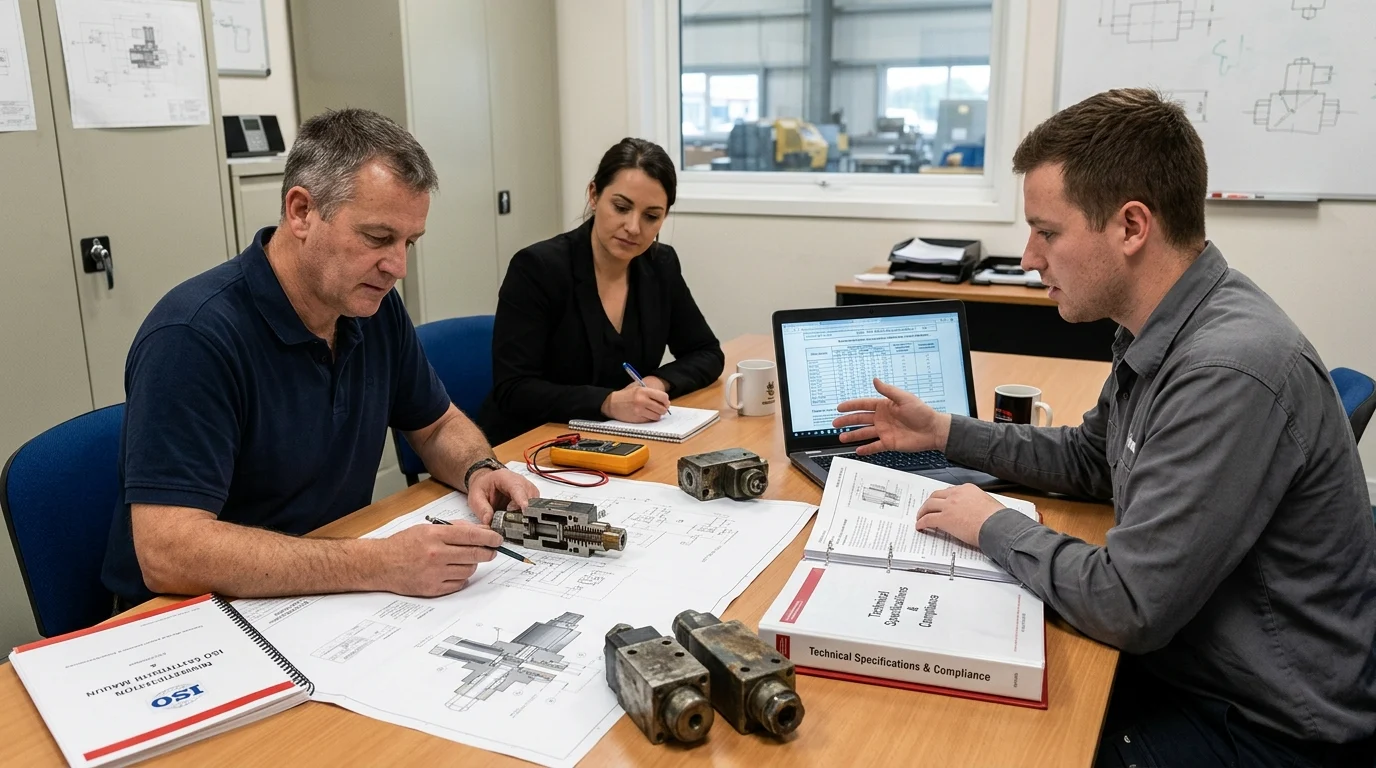
Evaluating hydraulic solenoid valves for integration into North American mobile equipment requires technical scrutiny from procurement and engineering teams. Original Equipment Manufacturers (OEMs) must balance hydraulic efficiency, electrical reliability, and environmental resilience. Flying Bull’s engineering framework facilitates this evaluation by providing architectural data and compliance documentation to support integration into complex, electronically controlled hydraulic circuits.
Valve Architecture Comparison
Mobile equipment designers primarily select between direct-acting and pilot-operated solenoid architectures based on flow requirements, pressure boundaries, and available electrical power. Direct-acting valves offer faster response times for low-flow pilot circuits, while pilot-operated configurations multiply the solenoid’s magnetic force to manage high fluid volumes without requiring excessive electrical current draw from the machine’s alternator. Flying Bull’s product portfolio covers these primary categories, allowing OEMs to select the appropriate architecture based on the general industry parameters outlined below.
| Architecture Type | Max Flow Rate | Typical Pressure Limit | Response Time | Common Application |
|---|---|---|---|---|
| Direct-Acting | Up to 30 L/min | 350 bar | 15-25 ms | Pilot controls, braking |
| Pilot-Operated | Up to 150 L/min | 420 bar | 30-50 ms | Main implement control |
| Proportional | Variable | 350 bar | 40-60 ms | Variable displacement pumps |
Testing Documentation and Certification Review
Compliance in the North American market dictates adherence to environmental and electrical durability standards. Solenoid coils must achieve IP67 or IP69K ingress protection ratings to survive high-pressure washdowns and continuous exposure to mud, dust, and corrosive de-icing salts. Flying Bull provides Production Part Approval Process (PPAP) documentation, including Level 3 submissions for mission-critical components. Validation protocols align with industry standards, including electromagnetic compatibility (EMC) testing per ISO 13766, thermal shock testing across a gradient from -40°C to +105°C, and impulse fatigue testing designed to exceed 2 million cycles at elevated operating pressures. This empirical data allows OEM engineers to verify that the specified valves can support the extended service life expected of heavy construction machinery.
Supplier Approval Decision Process
Integrating a new hydraulic component manufacturer into an established OEM supply chain requires cross-functional alignment. For North American equipment builders, approving Flying Bull as a tier-one or tier-two vendor involves a structured progression from initial commercial discussions to field validation. Rather than relying solely on standard procurement steps, Flying Bull emphasizes its specific track record of adapting to OEM engineering requirements, mitigating supply chain risks, and stabilizing production schedules before full-scale manufacturing begins.
RFQ, Sample Review, and Validation Steps
The approval sequence initiates with a Request for Quotation (RFQ), requiring the supplier to provide cost breakdowns, tooling requirements, and initial Design Failure Mode and Effects Analysis (DFMEA). Upon commercial alignment, the sample review phase begins. Flying Bull supports this phase through rapid prototyping, aiming to deliver A-samples within a standard 4-to-6-week lead time. These initial units undergo bench validation at the OEM level, focusing on hysteresis curves, internal leakage rates, and coil resistance at elevated operating temperatures. Successful bench testing transitions to B-sample integration, where Flying Bull’s valves are installed on prototype machinery for extended field testing under actual duty cycles to validate dynamic performance and operator feel.
Final Supplier Selection Criteria
Final supplier selection hinges on quantitative performance metrics and operational stability. North American OEMs require adherence to stringent quality thresholds, often targeting low Parts Per Million (PPM) defect rates. Flying Bull supports these targets through automated end-of-line testing for 100% of manufactured valves, verifying pressure limits and electrical continuity. Furthermore, commercial viability is assessed through Minimum Order Quantities (MOQs) and scalable production capacity. By offering adaptable MOQ structures and the capacity to scale output in response to market shifts, Flying Bull provides the flexibility to accommodate cyclical construction equipment demand.
Key Takeaways
- Specify valves for continuous pressures near 350 bar and intermittent spikes up to 420 bar when designing for heavy-duty mobile hydraulic systems.
- Match valve flow capacity to the circuit, from roughly 20 L/min pilot functions to 150 L/min main implement controls.
- Target pressure drops below 5 bar at maximum rated flow to reduce heat generation and improve hydraulic efficiency.
- Use proportional solenoid valves with sub-30-millisecond response targets where smooth excavator implement control is required.
- Select direct-acting valves for low-flow, fast-response circuits and pilot-operated valves for high-flow applications with limited electrical power.
- Evaluate spool hardness, sleeve precision, and micron-level clearances to reduce leakage and maintain actuation reliability under vibration.
Frequently Asked Questions
What pressure range defines a high-pressure hydraulic solenoid valve for mobile machinery?
In construction equipment, high-pressure hydraulic solenoid valves commonly operate around 350 bar (5,075 PSI) continuously and should tolerate intermittent spikes up to about 420 bar (6,090 PSI).
Why does flow capacity matter in construction machinery valves?
Flow capacity affects machine speed, control response, and productivity. Pilot circuits may need about 20 L/min, while main implement controls can require up to 150 L/min.
Where are hydraulic solenoid valves used in excavators and loaders?
They control functions such as boom hoist, bucket curl, track drive propulsion, auxiliary attachments, and hydrostatic transmission modulation in excavators, skid steers, and compact track loaders.
What response time is expected for smooth excavator control?
For a standard 20-ton excavator, proportional solenoid valves may need step-response times under 30 milliseconds to support smooth operator feedback and precise implement control.
How can valve design reduce hydraulic heat generation?
Optimized spool and gallery geometry can reduce pressure drop, ideally below 5 bar at rated flow, which limits wasted energy and lowers parasitic heat in compact engine compartments.
Post time: Sep-14-2026