
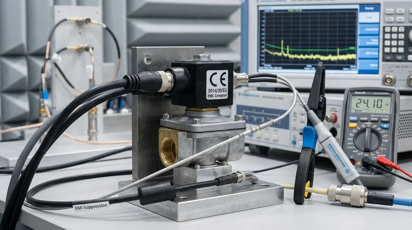
A solenoid coil may look like a simple actuator, but inside an industrial control system it can become a significant source of electromagnetic disturbance. Every switching event releases stored magnetic energy, and without proper suppression that energy can appear as high-voltage transients, conducted noise, relay arcing, or corrupted PLC communications. For equipment sold in the EU, these effects are not just reliability concerns—they directly affect conformity with Directive 2014/30/EU. This article explains how EMC applies to solenoid coils, why emissions and immunity must be considered together, and what design factors engineers should address to reduce interference before it becomes a compliance or production problem.
Why EMC Matters in Solenoid Coils
Electromagnetic Compatibility (EMC) is a critical compliance metric for industrial equipment incorporating solenoid coils. Under EU Directive 2014/30/EU, electrical and electronic equipment must function without introducing intolerable electromagnetic disturbances to other equipment, while also maintaining a specified level of immunity against external interference. Failure to comply can result in product recalls, financial penalties, and market exclusion.
Because solenoid coils are inherently inductive loads, they pose unique challenges to system-level EMC compliance during switching operations. The energy stored within the coil’s magnetic field must be managed properly to prevent electrical transients from compromising the entire industrial control system.
Emissions and Immunity Basics
The dual pillars of electromagnetic compatibility are emissions and immunity. Emissions refer to the electromagnetic energy generated by a device, whereas immunity denotes the equipment’s ability to operate reliably in the presence of external electromagnetic noise. In solenoid applications, the primary compliance hurdles involve conducted and radiated emissions generated during the de-energization phase.
When the power to a standard 24V DC solenoid coil is abruptly interrupted, the rapid collapse of its magnetic field induces a high-voltage transient. Without appropriate mitigation, this back electromotive force (EMF) can generate voltage spikes exceeding 600V to 1,000V. These transients propagate backward through power supply lines as conducted emissions, potentially damaging adjacent sensitive electronic components and violating EU emission thresholds. It should be noted that transient voltage magnitudes vary widely depending on the specific application and coil design, so these numerical values serve as illustrative baselines.
Common EMC Risks in Coil Applications
Unmitigated transients from solenoid coils introduce operational risks within complex industrial control panels. High-frequency noise, typically spanning the 150 kHz to 30 MHz spectrum, can couple into adjacent communication cables. This coupling frequently causes data packet corruption in Programmable Logic Controllers (PLCs) and industrial Ethernet networks, leading to spontaneous system resets or erroneous sensor readings.
Additionally, the high-voltage spikes lead to destructive arcing across electromechanical relay contacts used to switch the coils. This arcing accelerates contact material degradation, significantly reducing the mechanical switch lifespan and introducing further broadband radiated noise. Ensuring EMC compliance at the coil level mitigates these risks, safeguarding the continuous operation of automated manufacturing processes.
Key Factors Affecting EMC Performance
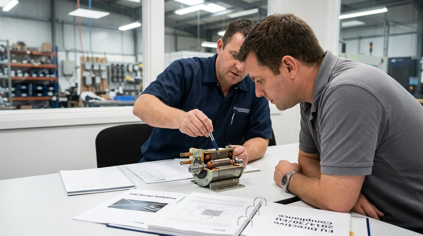
The electromagnetic compatibility profile of a solenoid coil is governed by its physical construction, the characteristics of its driving circuit, and the integration of transient suppression mechanisms. Understanding these variables is essential for engineers aiming to minimize electromagnetic interference at the source rather than relying solely on heavy, expensive shielding.
Coil Design and Switching Behavior
The fundamental switching behavior of a solenoid coil is determined by its inductance and the speed of current interruption (di/dt). Industrial solenoids frequently feature inductance values ranging from 10 mH to over 500 mH. The stored energy, which scales linearly with inductance and quadratically with current ($E = \frac{1}{2}LI^2$), must be dissipated safely upon switch-off.
When solenoids are driven by modern solid-state relays or Pulse-Width Modulation (PWM) controllers operating at high frequencies—often between 10 kHz and 20 kHz to reduce holding power—the rapid change in current generates significant high-frequency harmonics. Because PWM frequencies, coil inductance ranges, and operating parameters vary widely by manufacturer and application, these numerical values should be treated as illustrative rather than universal. These harmonics radiate outward as electromagnetic noise. Consequently, optimizing the switching speed to be as slow as permissible for the mechanical application can significantly reduce the amplitude of radiated emissions.
Suppression Method Comparison
Effective transient suppression is mandatory to align solenoid operation with EMC standards. The selection of a suppression device directly influences both the decay time of the magnetic field and the peak transient voltage. These performance metrics depend heavily on the specific coil inductance, operating voltage, current, and load mechanics. Common solutions include freewheeling diodes, Metal Oxide Varistors (MOVs), and Resistor-Capacitor (RC) snubbers.
| Suppression Method | Peak Transient Voltage | Drop-out Delay | Best Application |
|---|---|---|---|
| Freewheeling Diode | ~0.7V | High (up to 50ms) | DC circuits only, where speed is non-critical |
| MOV (Varistor) | Clamping Voltage (e.g., 47V) | Medium (10-20ms) | AC and DC circuits requiring moderate speed |
| RC Snubber | Variable (depends on tuning) | Low (<10ms) | AC and DC circuits preventing contact arcing |
Note: All numerical values in the table above (e.g., 47V clamping, 50ms drop-out, <10ms) are order-of-magnitude examples. Actual values must be recalculated for the specific coil, voltage, current, and load.
While the table outlines baseline performance, engineers must carefully weigh these trade-offs against functional requirements and failure modes. Crucially, suppression choices directly affect solenoid drop-out time, contact life, and safety response times, so selection must be validated against functional and safety requirements—not just EMC limits. A standard flyback diode offers excellent emission control but significantly increases mechanical drop-out time. Conversely, an MOV provides a balance between fast drop-out and moderate emission control, but degrades over time with repeated transient absorption. MOV and RC-snubber values must be explicitly selected for AC or DC service. If incorrectly specified for DC circuits, MOVs can suffer from continuous leakage current leading to thermal runaway. RC snubbers require precise tuning to the specific coil’s load to prevent resonance issues.
Meeting EU EMC Directive Requirements
Achieving compliance with EU Directive 2014/30/EU requires a formalized approach to both system evaluation and component procurement. The directive dictates that finished electrical apparatus placed on the European market must undergo a conformity assessment and bear the CE mark. Furthermore, comprehensive Technical Documentation must be maintained. The manufacturer or importer is legally obligated to make this documentation available to national authorities for 10 years after the equipment is placed on the market.
It is crucial to note that the EMC Directive’s CE marking obligations generally apply to the finished apparatus. Basic components like individual solenoid coils, which lack an intrinsic function on their own, are generally outside the Directive’s CE-marking scope.
Key Takeaways
- Treat solenoid coils as EMC-critical components because their inductive energy can generate damaging switch-off transients if not properly controlled.
- Design suppression for the actual coil and circuit, since a nominal 24V DC solenoid can produce transient spikes above 600V to 1,000V in some applications.
- Focus on conducted and radiated emissions during de-energization, especially in the 150 kHz to 30 MHz range where industrial control systems are vulnerable.
- Reduce EMC risk at the source by managing coil inductance, current interruption speed, wiring layout, and transient suppression before relying on shielding alone.
- Validate solenoid-based equipment against EU Directive 2014/30/EU requirements for both emissions control and immunity to external electromagnetic disturbance.
Frequently Asked Questions
Why do solenoid coils create EMC problems?
Solenoid coils are inductive loads, so when current is switched off, the collapsing magnetic field can generate high-voltage transients. These spikes can travel through power lines or radiate into nearby cables, causing interference in PLCs, sensors, relays, and industrial networks.
What does EU Directive 2014/30/EU require for equipment using solenoid coils?
The directive requires electrical and electronic equipment to avoid producing unacceptable electromagnetic disturbances and to maintain adequate immunity to external interference. For solenoid-based equipment, transient suppression and system-level EMC validation are essential.
How high can voltage spikes from a 24V DC solenoid become?
In poorly suppressed applications, a 24V DC solenoid can generate back-EMF spikes exceeding 600V to 1,000V during de-energization. Actual values depend on coil design, wiring, switching speed, and the suppression method used.
Which EMC risks are most common in industrial solenoid applications?
Common risks include conducted emissions on power lines, radiated noise into communication cables, relay contact arcing, PLC data errors, sensor misreadings, and unexpected controller resets. These issues are especially relevant in dense control panels.
What frequency range is often affected by solenoid switching noise?
Solenoid switching noise often affects the 150 kHz to 30 MHz range, where conducted emissions are commonly evaluated. Noise in this band can couple into control wiring and industrial Ethernet or fieldbus communication lines.
Post time: Jul-15-2026