
Introduction
After water ingress, a solenoid coil may still look serviceable while its insulation has already weakened enough to cause leakage, nuisance trips, or downstream control damage. This article explains when insulation resistance testing is necessary, how to prepare the circuit safely under typical European field conditions, and what checks to complete before any measurement is taken. You will learn the practical sequence technicians use to assess a wet or suspect coil, recognize warning signs such as casing damage or terminal corrosion, and decide whether the component can be returned to service or should be replaced before re-energizing the system.
When to Test Solenoid Coil Insulation Resistance After Water Ingress
Water ingress is a primary cause of solenoid coil failure in industrial and mobile machinery. When exposed to harsh weather, equipment washdowns, or localized flooding, moisture compromises the dielectric strength of the coil’s epoxy or thermoplastic encapsulation. Even components boasting robust IP65 or IP67 ratings under IEC 60529 standards can experience ingress if rapid thermal cycling creates an internal vacuum effect, drawing ambient moisture through micro-cracks or compromised seals.
Testing insulation resistance (IR) becomes a critical diagnostic step before re-energizing the system. Failing to verify the dielectric integrity of a wet coil can lead to catastrophic short circuits, blown fuses, or severe damage to upstream logic boards and programmable controllers.
Applicable conditions and safety checks
Field technicians must initiate testing whenever a solenoid valve exhibits erratic actuation, repeatedly trips overcurrent protection devices, or has been visibly submerged in water. Before attaching any diagnostic equipment to the affected machinery, strict safety protocols are mandatory. Technicians must verify that the control circuit is completely de-energized, utilizing lockout/tagout (LOTO) procedures to ensure zero residual voltage remains in the system.
A preliminary visual inspection is necessary to identify cracked casings, swollen potting compounds, or terminal corrosion. If the external housing or the DIN connector holds standing water, it must be thoroughly drained and wiped dry. Leaving surface water on the component can create conductive tracking paths, which will severely skew the diagnostic measurements and yield false failure readings.
Required tools and pre-test preparation
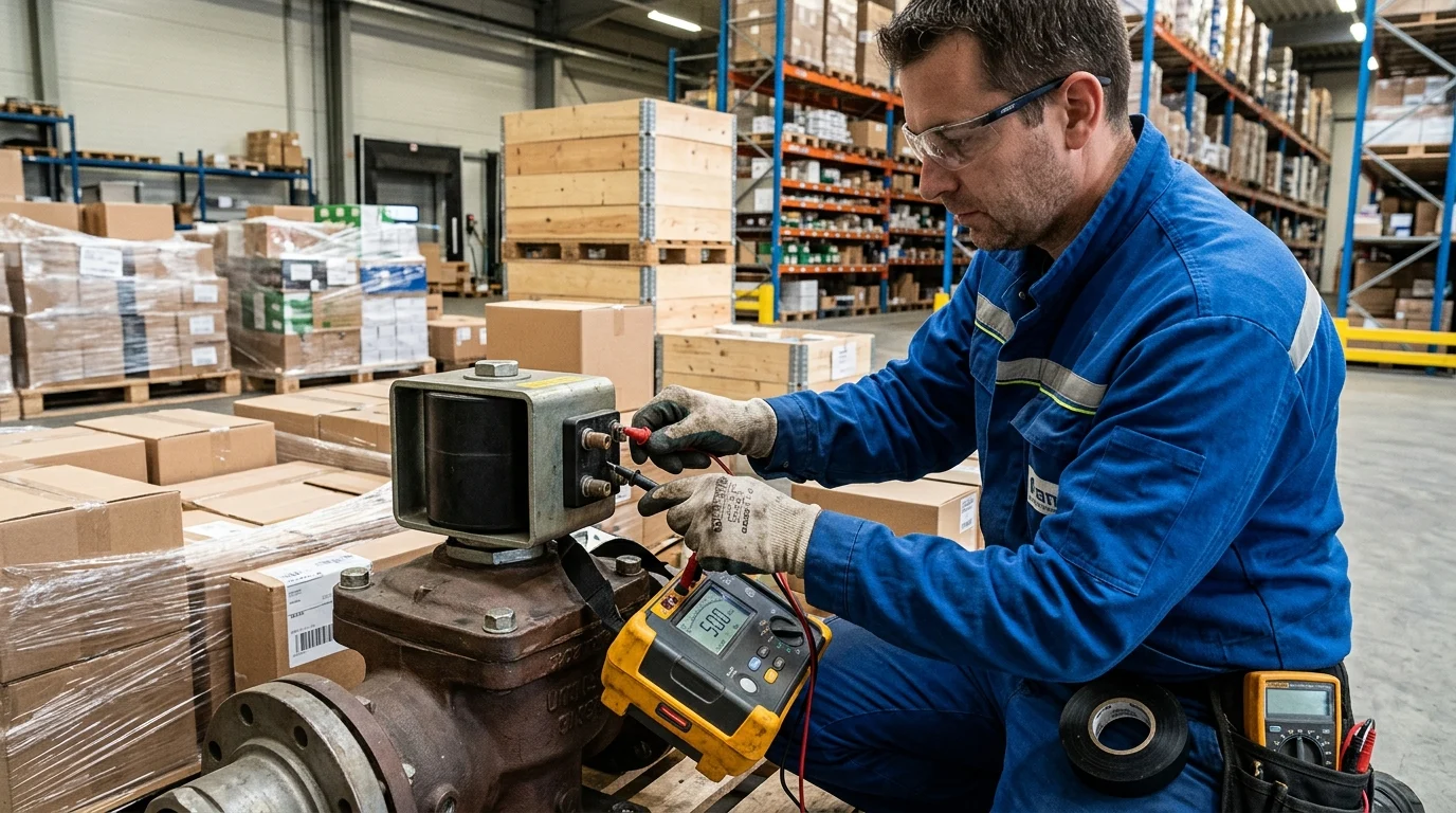
The primary instrument required for this diagnostic protocol is an insulation resistance tester, commonly referred to as a megohmmeter. Standard digital multimeters are insufficient for this task because they typically output less than 9V DC. This low voltage cannot adequately stress the dielectric material to reveal moisture-induced micro-faults deep within the copper windings.
A megohmmeter capable of outputting 500V DC is the industry standard for testing common 12V, 24V, and 110V/220V solenoid coils. In addition to the megohmmeter, technicians should prepare dielectric contact cleaners, lint-free cloths, and a standard digital multimeter. The standard multimeter is used first to verify baseline copper winding continuity—typically ranging from 10 to 100 ohms depending on the specific coil wattage—before proceeding to the high-voltage insulation test.
How to Test Solenoid Coil Insulation Resistance
Executing the insulation resistance test requires precision and strict adherence to protocol to ensure an accurate assessment of the coil’s internal dielectric health. The procedure involves applying a high direct current voltage across the insulation boundary to measure the minuscule leakage current. The test instrument then translates this micro-amperage into a readable megohm (MΩ) value.
Step-by-step field procedure
First, disconnect the solenoid coil completely from the control wiring to isolate it electrically. Failing to isolate the coil may push the 500V DC test voltage into sensitive programmable logic controllers (PLCs) or relay modules, causing instantaneous and permanent hardware damage. Once isolated, connect the positive (red) lead of the megohmmeter to one of the coil’s electrical spade terminals or flying leads.
Next, attach the negative (black) ground lead directly to the metallic valve body, the magnetic core tube, or the designated ground pin, ensuring a clean, rust-free connection point. Select the 500V DC test voltage setting on the meter. Depress the test button and maintain the applied voltage for exactly 60 seconds. This specific duration is critical; it allows the initial capacitive charging current and the dielectric absorption current to decay, leaving only the true leakage current flowing through the moisture-compromised insulation.
How to record readings and avoid test errors
Accurate record-keeping is vital for predictive maintenance and historical tracking. Technicians must document the ambient temperature, relative humidity levels, and the exact resistance value captured at the 60-second mark. Temperature significantly impacts dielectric materials; for every 10°C increase in ambient temperature above a baseline of 20°C, the measured insulation resistance effectively halves. Technicians must mathematically adjust field readings to standardize the data for accurate historical comparison.
To prevent severe measurement errors, technicians must ensure their hands do not touch the bare test leads, alligator clips, or the coil housing during the test. Human body resistance can introduce parallel leakage paths, artificially lowering the megohm reading. Furthermore, surface moisture on the coil’s exterior can cause superficial tracking. If a coil initially tests poorly, wiping the exterior with a rapid-evaporating dielectric solvent and retesting can determine whether the moisture has penetrated the internal windings or is merely a surface anomaly.
How to Interpret Results and Decide Next Actions
Once the 60-second insulation resistance values are recorded and temperature-corrected, technicians must evaluate the data against established industry thresholds to determine the operational viability of the solenoid valve. Proper interpretation prevents the dangerous reinstallation of compromised components that could cause unplanned facility downtime or safety hazards.
Pass-fail criteria and comparison points
Evaluation metrics depend heavily on the nominal operating voltage of the system and the severity of the water ingress. A general electrical rule of thumb requires at least 1 megohm (MΩ) of resistance per kilovolt of operating voltage, plus a baseline of 1 MΩ. However, for low-voltage industrial solenoids (such as 12V to 24V DC mobile equipment valves), stricter minimums are enforced to guarantee logic circuit stability.
The following table outlines standard evaluation thresholds for solenoid coil insulation resistance, assuming values have been normalized to an ambient temperature of 20°C:
| Condition | Insulation Resistance Range | System Impact / Status |
|---|---|---|
| Critical Failure | < 1.0 MΩ | High risk of short circuit; immediate removal required. |
| Marginal / Wet | 1.0 MΩ – 5.0 MΩ | Moisture present; potential for erratic operation. |
| Acceptable | 5.0 MΩ – 20.0 MΩ | Safe to operate, but monitor during next cycle. |
| Optimal | > 20.0 MΩ | Excellent dielectric strength; fully operational. |
Repair, drying, or replacement decisions
Coils falling into the marginal category (1.
Key Takeaways
- The most important conclusions and rationale for How to Test Solenoid Coil Insulation Resistance After Water Ingress: A European Field Technician‘s Protocol
- Specs, compliance, and risk checks worth validating before you commit
- Practical next steps and caveats readers can apply immediately
Frequently Asked Questions
When should a solenoid coil be tested for insulation resistance after water ingress?
Test it before re-energizing if the coil was submerged, exposed to washdown, actuates erratically, or repeatedly trips overcurrent protection.
Can I use a standard multimeter to check insulation resistance?
No. Use a megohmmeter set to 500V DC; a standard multimeter lacks enough test voltage to reveal moisture-related insulation faults.
How should the coil be connected during the IR test?
Fully isolate the coil from control wiring, connect the positive lead to a coil terminal, and the negative lead to the valve body or core tube.
How long should the 500V insulation resistance test be applied?
Apply the test voltage for 60 seconds and record the reading at the 60-second mark for a reliable leakage value.
What reading practices help avoid false insulation resistance results?
Drain and dry surface water first, avoid touching bare leads or the housing during the test, and note temperature and humidity with the reading.
Post time: Jun-05-2026