
In dense European rail corridors, a delayed or failed point movement can ripple through timetables within minutes—and in the worst case, compromise route safety. At the center of this electromechanical chain is the solenoid coil, the component that turns an interlocking command into controlled motion and secure locking. Specifying it correctly means looking beyond nominal voltage or package size. Engineers must evaluate SIL 4 reliability targets, pull-in force margins, stroke accuracy, thermal class, magnetic efficiency, vibration endurance, and voltage drop across long trackside cable runs. This article examines the practical performance criteria that determine whether a coil can support safe, repeatable turnout operation in demanding European signaling environments.
Role of Solenoid Coils in Railway Signaling Systems
Operating within the overarching framework of the European Rail Traffic Management System (ERTMS), electromechanical actuators translate electrical command signals into the physical kinetic force required to actuate and secure point machines. Within these turnout and point control mechanisms distributed across European rail networks, solenoid coils function as the critical energy-conversion components. The precision of this conversion directly dictates the operational fluidity of high-density rail corridors, where even minor actuation delays can cascade into significant network disruptions.
Reliability Impact in Safety-Critical Applications
In safety-critical railway applications, the reliability of a solenoid coil is paramount. European rail authorities mandate strict adherence to Safety Integrity Level 4 (SIL 4) standards for point machine locking mechanisms, requiring the probability of dangerous failure per hour (PFHD) to remain strictly below 10^-9, though specific targets can vary by national safety authority. A coil failure in a turnout mechanism can result in route locking failures, causing severe network delays or catastrophic derailment risks. Consequently, modern signaling coils are engineered for extreme longevity, with Mean Time Between Failures (MTBF) often targeted to exceed 2.5 million hours depending on manufacturer specifications. This reliability must be sustained under continuous, high-amplitude vibration profiles generated by passing high-speed and heavy-freight trains, necessitating robust internal structural support and specialized winding techniques that prevent micro-abrasions in the wire enamel.
Key Definitions and System Interfaces
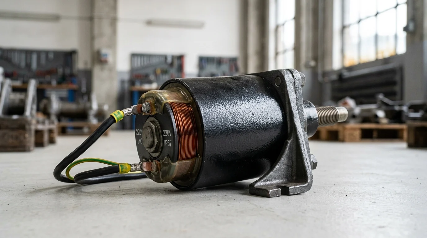
Defining the operational envelope requires a thorough understanding of the system interfaces between the trackside interlocking logic controller and the physical point machine. The solenoid coil typically acts as the pilot stage for hydraulic systems or as the direct locking actuator in electromechanical setups. Key definitions include the “pull-in force,” which must be sufficient to overcome mechanical stiction, rail expansion friction, and environmental ice buildup. In heavy-rail applications, this often requires a transient force generation exceeding 5,000 Newtons. The mechanical interface also demands precise stroke calibration, typically ranging from 15 mm to 45 mm. This exact travel distance ensures that the locking dogs fully engage the stretcher bars before the signaling system’s microswitches register a positive detection state and transmit the locked confirmation back to the control center.
Technical Specifications for Solenoid Coil Performance
Specifying solenoid coils for trackside point machines requires a rigorous evaluation of electromagnetic performance against the harsh, unforgiving operating environments of railway infrastructure. Engineers must carefully balance the required actuation force with strict power budgets, which are often heavily constrained by voltage drops across long-distance cable runs extending from interlocking equipment rooms to remote field devices.
Electrical, Magnetic, and Thermal Requirements
Electrical and magnetic efficiency rely heavily on optimal winding parameters and the selection of high-grade raw materials. To withstand continuous holding currents and high ambient trackside temperatures, coils must utilize Class H insulation, which is rated for thermal endurance up to 180°C. The magnetic circuit, comprising the armature and the yoke, is typically machined from low-carbon steel or specialized ferromagnetic alloys designed to minimize hysteresis and eddy current losses.
Furthermore, dielectric strength is a critical parameter for trackside safety. Signaling coils are routinely subjected to high-voltage testing, required to withstand 2,500V AC for 60 seconds without insulation breakdown. This ensures absolute isolation integrity against lightning strikes, power surges, and severe traction return current transients that frequently occur in electrified rail networks.
Comparison Criteria for Voltage, Duty Cycle, and Environment
Evaluating and comparing coils requires a systematic look at voltage inputs, duty cycles, and environmental sealing capabilities. Point control systems operate on varied power architectures depending on whether they are installed on legacy regional lines (e.g., relay-based interlockings) or newly constructed ERTMS high-speed corridors. It is also important to note that ERTMS Levels 1 and 2 differ in their point machine control architectures, imposing varying solenoid specifications rather than a monolithic standard. Below is a comparative baseline for typical trackside solenoid specifications based on application requirements:
| Specification Parameter | Standard Point Lock | Heavy-Duty Actuator | High-Speed Turnout |
|---|---|---|---|
| Operating Voltage | 24V DC / 48V DC | 110V DC | 230V AC (Rectified) |
| Duty Cycle Rating | 100% ED (Continuous) | 40% ED (Intermittent) | 100% ED (Continuous) |
| Max Inrush Current | < 2.5 Amps | < 8.0 Amps | < 4.5 Amps |
| Ingress Protection | IP67 | IP68 | IP69K |
| Temperature Range | -25°C to +70°C | -40°C to +85°C | -40°C to +85°C |
Coils specified with a 100% ED (Einschaltdauer, or relative duty cycle) continuous rating are vital for failsafe locking mechanisms that remain energized for hours, whereas 40% ED variants are optimized for high-force, short-duration throw operations. The shift toward IP69K ratings for high-speed turnouts reflects the necessity for coils to survive aggressive trackside maintenance, where aerodynamic fouling necessitates high-pressure washing and prolonged exposure to anti-icing chemicals during severe Alpine winters.
Supplier Qualification and Sourcing Decisions
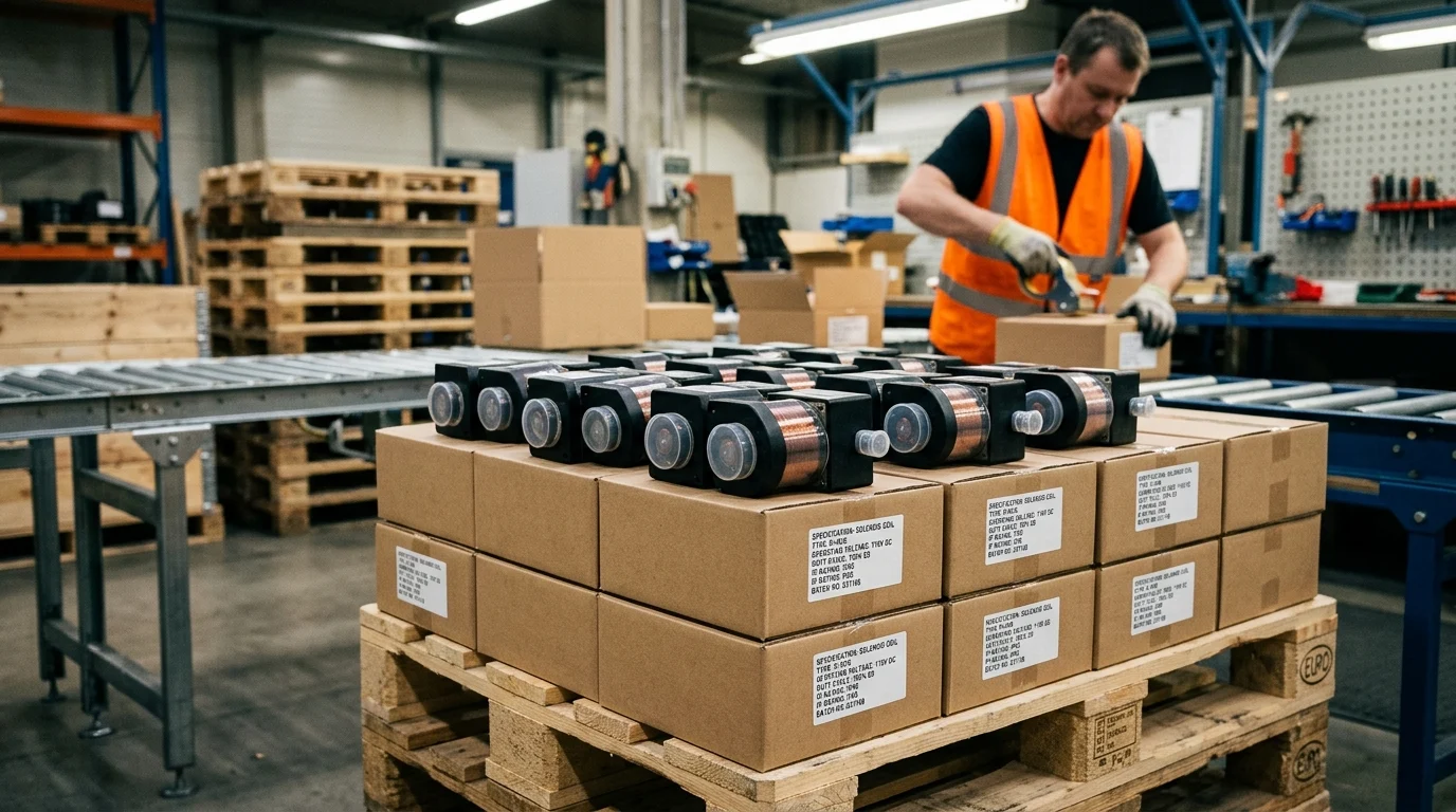
Procuring electromechanical components for European rail infrastructure necessitates a highly structured and risk-averse supply chain strategy. Sourcing decisions extend far beyond initial unit costs, focusing instead on total lifecycle management, component traceability, and stringent adherence to European Norms (EN) governing railway applications.
Compliance, Documentation, RAMS, and EMC Requirements
Suppliers entering this space must demonstrate comprehensive compliance with the EN 5012x series of standards. Specifically, EN 50121-4 dictates Electromagnetic Compatibility (EMC) for trackside equipment, ensuring that solenoid coils neither emit disruptive radio-frequency interference nor succumb to the intense electromagnetic noise generated by 25kV AC traction systems. Furthermore, EN 50129 governs Reliability, Availability, Maintainability, and Safety (RAMS), requiring manufacturers to provide detailed Failure Mode, Effects, and Criticality Analysis (FMECA) documentation. Quality control thresholds in this sector are exceptionally strict; component manufacturers typically must maintain defect rates below 50 Parts Per Million (PPM) to qualify for Tier-1 signaling contracts, as any failure in the field incurs exorbitant replacement costs and network penalties.
Practical Supplier Assessment Process
A practical supplier assessment involves rigorous, multi-day auditing of the manufacturer’s quality management systems and production facilities.
Key Takeaways
- Specify solenoid coils against SIL 4 safety expectations, including a dangerous failure probability target typically below 10^-9 per hour for point locking functions.
- Design for high durability by targeting MTBF values that can exceed 2.5 million hours and by using winding methods that resist vibration-induced enamel abrasion.
- Confirm that pull-in force exceeds the mechanical worst case, which in heavy-rail turnout applications may require transient force above 5,000 N.
- Calibrate actuator stroke within the required point machine travel range, commonly 15 mm to 45 mm, so locking dogs engage before detection is confirmed.
- Use Class H insulation rated to 180°C where coils must tolerate continuous holding current and elevated trackside temperatures.
- Account for voltage drop across long field cables when balancing coil voltage, resistance, magnetic force, and available interlocking power.
Frequently Asked Questions
Why are solenoid coils critical in railway turnout control?
They convert electrical commands from signaling or interlocking systems into the mechanical force needed to actuate or lock point machines. Reliable coil performance helps prevent route locking failures, delays, and safety risks.
What reliability level is expected for point machine locking coils?
European safety-critical applications commonly target SIL 4 performance, with dangerous failure probability typically below 10^-9 per hour. Many modern designs also aim for MTBF figures exceeding 2.5 million hours.
How much force should a turnout solenoid coil provide?
Heavy-rail applications may require transient pull-in force above 5,000 N to overcome stiction, rail expansion friction, contamination, or ice buildup. The exact requirement depends on point machine design and site conditions.
What stroke range is typical for point machine solenoid actuation?
Stroke calibration is often in the 15 mm to 45 mm range. Correct travel ensures locking components fully engage before detection switches confirm the point position to the signaling system.
Why is Class H insulation used in railway solenoid coils?
Class H insulation is rated up to 180°C, making it suitable for continuous holding currents, heat generated inside the winding, and elevated ambient temperatures in trackside cabinets or exposed environments.
Post time: Jun-22-2026