
Introduction
In valve-based safety functions, the solenoid coil is not a minor accessory; it is often the element that determines whether a commanded safe state is actually achieved. This article explains how coils affect ISO 13849 assessments for European machinery, with a focus on calculating the required and achieved performance level for valve systems. You will see why coil failure modes, diagnostic coverage, mission profile, and reliability data matter when estimating PFH_D and validating a safety function from PL c to PL e. The discussion then leads into the practical steps engineers use to evaluate coil contribution within the broader SRP/CS architecture.
Coils in Functional Safety
In the context of European machinery safety, compliance with ISO 13849-1 requires rigorous evaluation of all components that execute safety functions. Solenoid coils, acting as the critical electromechanical interface in fluid power and pneumatic valve systems, are fundamental to determining the achieved Performance Level (PL). Because valves often serve as the final control elements in safety-related parts of a control system (SRP/CS), the reliability of the actuating coil directly dictates whether the system can meet its Required Performance Level (PLr).
Depending on the severity of potential injury and the frequency of exposure, machinery applications typically demand a PLr ranging from PL c to PL e. A failure at the coil level—whether due to thermal degradation, electrical shorting, or mechanical binding of the armature—can compromise the entire safety loop. Consequently, engineers must evaluate coil specifications not just for operational efficiency, but for their mathematical contribution to the system’s overall probability of dangerous failure per hour (PFH_D).
Impact on risk reduction and machine uptime
The integration of highly reliable coils directly influences both the risk reduction capabilities and the operational uptime of industrial machinery. In safety loops, the coil is responsible for initiating the safe state, which typically involves de-energizing to vent or block fluid power. When a coil exhibits a Mean Time Between Failures (MTBF) exceeding 50,000 hours under rated thermal loads, it significantly lowers the PFH_D of the actuating subsystem.
Beyond pure safety, robust coil design minimizes spurious trips caused by voltage fluctuations or thermal overloads. Unplanned machine halts due to false safety triggers can incur severe production losses. By selecting coils with optimized magnetic flux and superior insulation classes (such as Class H, rated for 180°C), engineers ensure that the safety function remains vigilant without degrading the machine’s primary productive output.
When coil selection is safety-critical
Coil selection transitions from a standard engineering choice to a safety-critical mandate when the valve assembly controls hazardous motions, such as in mechanical presses, robotic workcells, or heavy lifting equipment. In these environments, the risk assessment typically dictates a PL d or PL e requirement, mandating redundancy (Category 3 or 4 architectures) and a high Diagnostic Coverage (DC).
In safety-critical scenarios, the response time of the coil becomes a paramount metric. A delay in the electromagnetic decay can extend the stopping time of a dangerous mechanical movement. Safety-rated coils are often specified to achieve de-energization and armature drop-out in under 20 milliseconds. If the coil’s inductive kickback is improperly managed by standard suppression diodes, this drop-out time can inadvertently stretch beyond 50 milliseconds, potentially violating the safety distance calculations established during the machine’s initial risk assessment.
How to Assess Safety-Relevant Coil Performance
Assessing the safety-relevant performance of a solenoid coil requires translating electromechanical characteristics into quantifiable reliability data. Under ISO 13849-1, components cannot be evaluated on functional merits alone; they must provide statistical evidence of their durability and failure modes. Machine builders must gather specific metrics from coil manufacturers to populate reliability block diagrams and validate the safety loop.
Key parameters, definitions, and calculation inputs
The most critical parameter for electromechanical components in ISO 13849-1 calculations is the B10d value, which represents the number of cycles until 10% of the components fail dangerously. For industrial pneumatic directional control valves and their actuating coils, a B10d rating of 20 million cycles is a standard benchmark for high-reliability applications. This figure is used in conjunction with the estimated annual operation cycles (nop) to calculate the Mean Time to Dangerous Failure (MTTFd).
Another vital input is the mission time (T_M), which ISO 13849-1 typically caps at 20 years. Regardless of the calculated MTTFd, the safety components—including the coils—must be replaced or thoroughly overhauled at the end of this mission time to prevent age-related wear-out failures. Furthermore, engineers must account for the Common Cause Failure (CCF) score, ensuring that redundant coils in a Category 3 or 4 system are protected against simultaneous failures from shared vulnerabilities like overvoltage or ambient temperature spikes.
Trade-offs between standard and safety-focused coils
Specifying coils for safety-critical valve systems involves navigating distinct trade-offs between standard commercial off-the-shelf (COTS) components and specialized safety-focused variants. While standard coils are optimized for cost and general continuous duty, safety-focused coils are engineered with predictable failure modes, tighter manufacturing tolerances, and enhanced diagnostic compatibilities.
| Specification/Metric | Standard Industrial Coil | Safety-Focused Coil |
|---|---|---|
| Typical B10d Rating | 5 to 10 million cycles | 20 to 40+ million cycles |
| Voltage Tolerance | ±10% of nominal | ±15% with guaranteed drop-out limits |
| Insulation Rating | Class F (155°C) | Class H (180°C) with thermal protection |
| Diagnostic Compatibility | None / basic LED indicator | Integrated current monitoring support |
| Cost Profile | Baseline | 15% to 30% premium |
The higher upfront cost of safety-focused coils is offset by their contribution to achieving a higher PL. Using standard coils in a high-demand safety system often forces engineers to implement complex, costly redundancies elsewhere in the architecture to compensate for the lower MTTFd. Conversely, safety-focused coils streamline compliance, reduce the required frequency of proof testing, and lower the total lifecycle cost of the safety system.
Practical Selection and Validation
Theoretical calculations must eventually translate into practical procurement, integration, and validation. For machine builders targeting the European market, proving that a valve system meets the PLr involves rigorous documentation and adherence to ISO 13849-2 validation protocols. Selecting the right components requires balancing stringent compliance thresholds with supply chain realities.
Step-by-step validation for machine builders
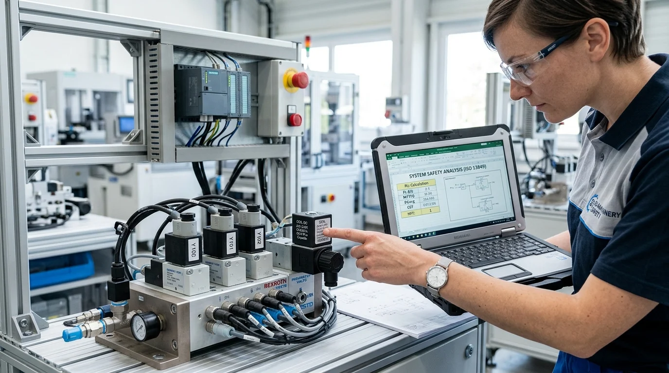
The validation process typically relies on software tools like SISTEMA (Safety Integrity Software Tool for the Evaluation of Machine Applications).
Key Takeaways
- The most important conclusions and rationale for The Role of Coils in Functional Safety (ISO 13849): Calculating PLr for Valve Systems in European Machinery
- Specs, compliance, and risk checks worth validating before you commit
- Practical next steps and caveats readers can apply immediately
Frequently Asked Questions
Why do solenoid coils matter in ISO 13849 valve safety calculations?
The coil executes the valve’s safe-state movement. If it fails dangerously, the valve may not vent or block power, lowering the achieved PL and risking noncompliance with the required PLr.
What coil data is needed to calculate PLr for a valve system?
Request B10d, operating cycles, mission time, response/drop-out time, insulation class, and any diagnostic or failure-mode data. These inputs support MTTFd, PFH_D, and category validation.
How does suppression affect coil safety response time?
Standard flyback diodes can slow de-energization and extend armature drop-out beyond safe limits. Use suppression designed for fast release when stopping time and safety distance are critical.
When should I choose a safety-focused coil instead of a standard coil?
Choose safety-focused coils when the valve controls hazardous motion and the risk assessment requires PL d or PL e. They are better suited for redundant architectures, faster release, and documented reliability data.
Do coils need replacement even if calculations show high reliability?
Yes. ISO 13849 assessments typically use a mission time capped at 20 years. Replace or overhaul coils by the defined mission time to avoid age-related wear and loss of safety performance.
Post time: Jun-08-2026