

In modern sequencing and diagnostic instruments, fluid control is not just a mechanical function—it directly influences assay accuracy, reagent cost, and sample integrity. Miniature solenoid coils provide the electromagnetic force behind fast, repeatable microvalve and micropump actuation, often handling microliter-scale fluid transfers across thousands of cycles. Selecting the right coil requires more than choosing a voltage or package size; engineers must weigh force, stroke, duty cycle, response time, heat rise, and manifold integration. This article explains the practical selection factors that matter most when designing compact analytical systems where precision fluid handling, thermal stability, and high-throughput reliability must all work together.
Role of Miniature Solenoid Coils in Analytical and Medical Systems
Miniature solenoid coils act as the electromagnetic engines of precision fluidic instruments, particularly within DNA sequencing platforms and in vitro diagnostic (IVD) systems. While the complete valve assembly handles direct fluid contact, the coil converts electrical energy into a magnetic field. This field acts upon a plunger or armature to produce the linear motion required to drive microvalves and micropumps. As Next-Generation Sequencing (NGS) devices shrink in footprint while increasing throughput, the demand for highly compact, reliable, and thermally efficient coils has surged to manage complex biochemical assays.
Fluid Control and Reagent Handling
At the operational level, the complete valve assembly governs the flow of buffers, enzymes, and sample fluids to prevent cross-contamination. The miniature solenoid coil provides the rapid actuation force for these pinch, isolation, and proportional valves. Operating at microliter-scale dispensing levels, these systems typically handle liquid volumes ranging from 1 to 50 microliters per actuation, though true microfluidic systems often operate at sub-microliter volumes. The coil’s rapid response ensures fluidic channels open and close with exact timing. This minimizes expensive reagent waste—a significant cost driver in genomic sequencing—and guarantees highly consistent volumetric ratios across thousands of test cycles.
Key Definitions and Performance Terms
Selecting the appropriate coil requires understanding specific electromechanical terms. “Duty cycle” dictates the ratio of energized time to total cycle time; continuous operation (100% duty cycle) generates substantial heat. “Response time” is the duration between voltage application and full armature actuation, with high-throughput sequencers often demanding sub-5-millisecond speeds. “Holding current” is the reduced electrical current required to keep the valve open after the initial “pull-in current” overcomes mechanical inertia. Engineers frequently use Pulse Width Modulation (PWM) to drop the holding voltage. While reductions of up to 70% are possible, the exact safe reduction depends on the specific valve-coil combination. This reduction must be rigorously validated against the minimum hold force required and allowable temperature rise, ensuring strict thermal management in temperature-sensitive diagnostic instruments.
Critical Specifications for Miniature Solenoid Coil Selection
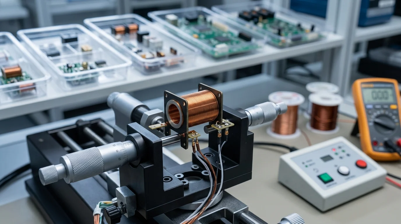
Engineering a fluidic system for medical diagnostics requires matching the miniature solenoid coil’s electromechanical properties to the assay protocol’s exact demands. Engineers must balance the instrument’s compact footprint with the magnetic flux required to drive the valve mechanism. Form factor, mounting, and integration constraints are often decisive; coils must fit tightly packed manifolds without causing magnetic interference between adjacent valves. Over-specifying the coil leads to unnecessary bulk, increased cost, and excessive heat generation, while under-specifying risks incomplete valve actuation or sluggish response times, directly compromising analytical accuracy.
Force, Stroke, Response Time, and Power Consumption
The fundamental performance triad for any miniature solenoid coil consists of force, stroke, and power consumption. The coil must generate sufficient magnetic force to overcome fluid pressure, valve spring return, and friction across a specific stroke distance. Power consumption is equally critical, as excess wattage translates directly into heat that can degrade temperature-sensitive reagents or denature DNA samples. Engineers size coils for their thermal budget using standard electrical relationships, though exact calculations depend on the drive topology. In constant-voltage systems, current ($I = V/R$) and power ($P = V^2/R$) fluctuate as copper wire resistance ($R$) increases with temperature, requiring careful calculation to prevent thermal drift. Constant-current drivers mitigate this by maintaining a steady magnetic force despite resistance changes. Additionally, coil inductance and the electrical time constant ($L/R$) strongly influence response time and heating, dictating how quickly the magnetic field builds upon actuation.
Note: The specifications provided in the table below are illustrative examples. Actual ranges for stroke length, response time, power consumption, and lifecycle figures vary widely depending on the manufacturer, specific valve design, and application requirements.
| Specification | Typical IVD Range | Impact on System Performance |
|---|---|---|
| Stroke Length | 0.1 mm – 2.0 mm | Determines maximum fluid flow rate and internal pressure drop. |
| Response Time | 2 ms – 15 ms | Directly affects sample throughput and dispensing accuracy. |
| Power Consumption | 0.5 W – 3.0 W | Influences thermal management and instrument power supply sizing. |
| Pull-in Force | 0.5 N – 5.0 N | Dictates the maximum fluid pressure the valve can effectively control. |
Materials, Insulation Class, and Environmental Fit
The operating environment within analytical systems necessitates careful selection of coil materials. Manufacturers utilize ultra-fine copper magnet wire, often ranging from AWG 36 to AWG 45, to maximize the number of turns within a miniature footprint. Bobbins are frequently molded from high-performance thermoplastics like Liquid Crystal Polymer (LCP) or Polybutylene Terephthalate (PBT) to withstand continuous thermal cycling without warping. Magnet wire insulation must align with the expected internal temperature rise; Class F (rated for 155°C) or Class H (rated for 180°C) insulation systems are standard choices to prevent short circuits during prolonged duty cycles.
Beyond electromechanical properties, engineers must address regulatory and biocompatibility considerations. Obligations under the FDA, IVDR, and ISO 13485 typically apply to the finished device, system, or complete valve subassembly; a raw coil is usually a component that is not independently certified. However, ISO 10993 testing remains relevant for any fluid-contacting components of the broader valve assembly. Material compatibility is paramount; engineers must determine whether the coil and its housing are positioned directly in the fluid path or isolated behind a flexible diaphragm. If exposed, materials must be chemically compatible with harsh sequencing reagents and aggressive cleaning agents. Even when isolated, epoxy-encapsulated or overmolded coils are highly recommended to protect fragile copper windings from condensation or accidental corrosive reagent spills, ensuring long-term reliability in high-humidity laboratory environments.
Sourcing and Validation Best Practices
Transitioning from theoretical design to component procurement involves rigorous validation protocols and strategic supplier selection. In the highly regulated medical device sector, the reliability of a single miniature solenoid coil can dictate the operational uptime of analytical instruments costing hundreds of thousands of dollars. Establishing robust sourcing practices requires addressing supply chain risks concretely through second-source qualification, strict change-control agreements, and comprehensive component traceability.
Key Takeaways
- Match coil force and stroke to the valve’s fluid pressure, spring return, and friction requirements to avoid incomplete actuation.
- Design for thermal limits early because continuous-duty operation can heat nearby reagents, enzymes, and DNA samples.
- Use PWM or reduced holding current only after validating minimum hold force and allowable temperature rise for the exact valve-coil pairing.
- For high-throughput sequencing systems, evaluate coils capable of rapid actuation, often in the sub-5-millisecond range.
- Avoid over-specifying coil size or power because unnecessary wattage increases heat, cost, and integration difficulty in compact manifolds.
- Consider magnetic spacing and mounting constraints when placing multiple coils in densely packed analytical or IVD fluidic assemblies.
Frequently Asked Questions
What does a miniature solenoid coil do in DNA sequencing or IVD instruments?
It converts electrical energy into a magnetic field that moves a plunger or armature, enabling microvalves and micropumps to control fluids with precise timing.
Why is thermal performance important when selecting a coil?
Excess heat can affect temperature-sensitive reagents, enzymes, or DNA samples, so coil power, duty cycle, and holding current must be matched to the assay requirements.
What response time is typically needed for high-throughput sequencing systems?
High-throughput platforms may require sub-5-millisecond actuation to coordinate rapid reagent delivery and maintain consistent test-cycle timing.
How does duty cycle affect solenoid coil selection?
A higher duty cycle means the coil stays energized longer and generates more heat, making thermal capacity and power reduction strategies critical.
Can PWM reduce solenoid coil power consumption?
Yes. Pulse Width Modulation can reduce holding voltage after pull-in, sometimes by up to 70%, but the safe reduction must be validated for each valve-coil design.
Post time: Jul-10-2026