
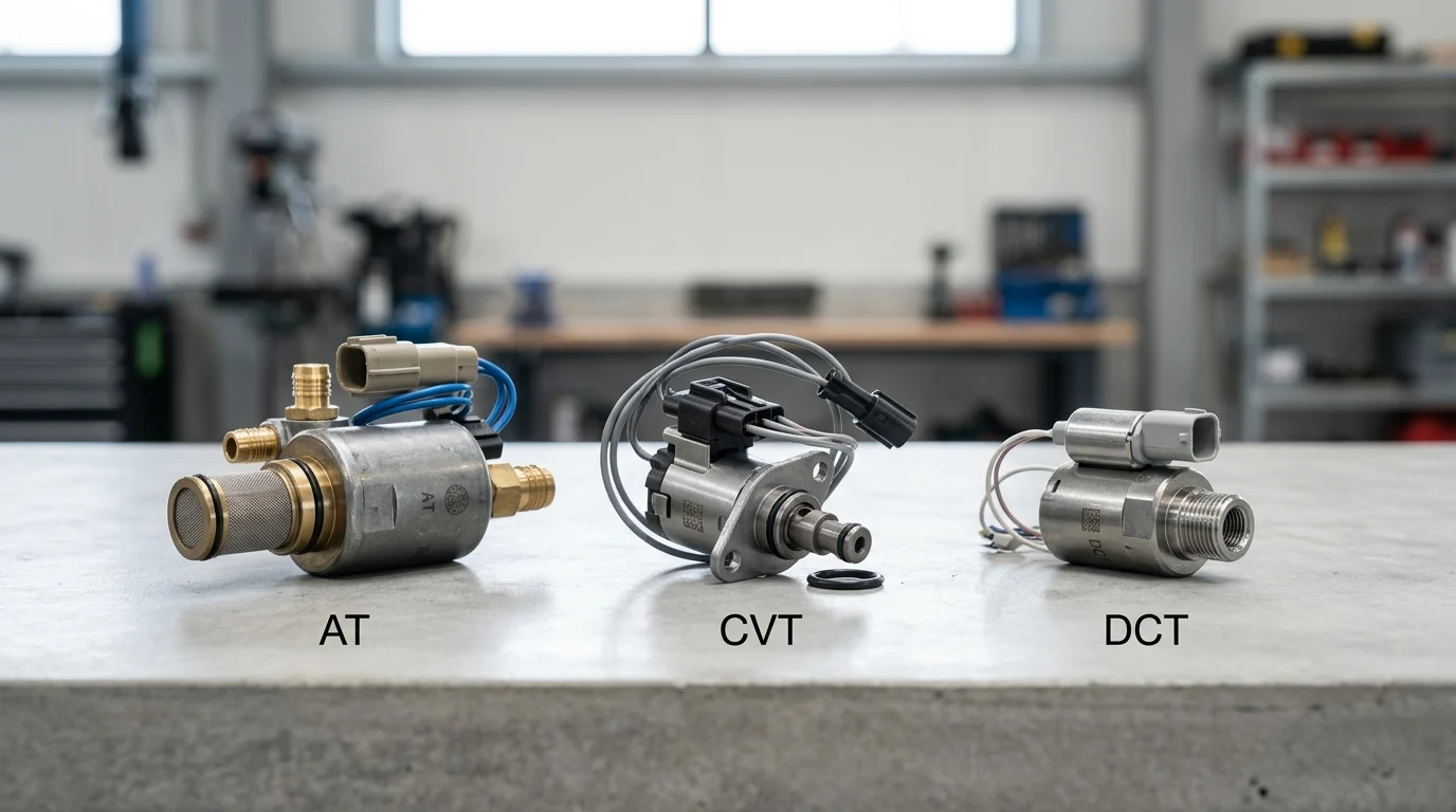
A transmission solenoid valve may look like a small component, but its job changes dramatically depending on the gearbox around it. In a step-gear automatic, it must smooth clutch-to-clutch pressure handoffs; in a CVT, it must hold extreme pulley clamping force; in a DCT, it must react fast enough to coordinate near-instant clutch swaps. These differences affect everything from pressure range and leakage limits to thermal stability, contamination tolerance, and supplier qualification. For engineers, buyers, and quality teams, understanding these application-specific requirements is essential to avoid shift complaints, belt slip, premature wear, and costly field failures.
AT, CVT, and DCT Solenoid Valve Differences
Transmission solenoid valves serve as the critical electro-hydraulic interface in modern automotive gearboxes, translating electronic control unit (ECU) signals into precise fluid power. While the fundamental electromagnetic principles remain consistent across platforms, the architectural divergence among gearboxes necessitates highly specialized valve designs.
Automatic Transmissions (AT), Continuously Variable Transmissions (CVT), and Dual-Clutch Transmissions (DCT) each impose distinct operational demands. Understanding these differences is essential for engineers and procurement specialists tasked with specifying hydraulic control components.
Core Functions by Transmission Type
In step-gear AT architectures, solenoid valves primarily manage clutch-to-clutch handoffs. These systems rely heavily on variable force solenoids (VFS) to modulate hydraulic pressure smoothly, ensuring seamless engagement and disengagement of planetary gear sets without torque interruption or harshness.
CVT applications demand a fundamentally different hydraulic strategy. The primary function of a CVT solenoid is to regulate the immense clamping forces on the variator pulleys to prevent belt or chain slip while simultaneously adjusting the sheave ratios. Because power transmission relies entirely on continuous friction, CVT valves must sustain exceptionally high continuous line pressures, often exceeding 60 bar in the primary circuit.
DCT systems prioritize actuation speed and gear pre-selection. Solenoids in a DCT control the dual wet or dry clutches alongside the mechanical shift forks. Because one clutch disengages exactly as the other engages, DCT valves require ultra-fast transient response capabilities to execute shifts in milliseconds, minimizing synchronization latency and maintaining continuous power delivery.
Key Engineering and Commercial Risks
Engineering risks vary significantly across gearbox topologies. CVT systems are highly susceptible to pressure micro-fluctuations; even a 0.5 bar deviation can induce macro-slip, leading to catastrophic variator scoring and transmission failure. DCT architectures face severe thermal degradation risks, as rapid sequential shifting generates localized heat spikes that can alter fluid viscosity and shift the valve’s response curves unpredictably.
Commercially, achieving economies of scale while maintaining rigorous quality control presents a substantial hurdle. Proportional solenoids feature intricate magnetic circuits and spool geometries with particle tolerances typically restricted to 15-25 microns. Manufacturers must balance aggressive cost-down targets with the strict necessity of maintaining sub-50 PPM (parts per million) defect rates, as a single valve failure in the field often necessitates a costly complete transmission teardown.
Technical Specifications and Validation Criteria

Qualifying a solenoid valve for an automotive transmission requires rigorous adherence to strict electro-hydraulic specifications. Engineers must evaluate static and dynamic metrics to ensure the valve performs reliably across the vehicle’s entire operational envelope and lifecycle.
Pressure, Flow, Response, and Leakage Metrics
Baseline performance metrics—operating pressure, flow capacity, step response, and internal leakage—dictate the fundamental suitability of a valve for a specific transmission type. Leakage limits are particularly stringent in modern architectures to minimize parasitic losses from the transmission’s hydraulic pump, with typical thresholds held strictly below 5 cc/min at a 10 bar pressure differential.
| Specification | AT (Variable Force) | CVT (High Pressure) | DCT (Direct Acting) |
|---|---|---|---|
| Max Operating Pressure | 15 – 20 bar | 40 – 60+ bar | 20 – 30 bar |
| Typical Response Time | 30 – 50 ms | 40 – 60 ms | < 15 ms |
| Flow Rate Capacity | High (10-15 L/min) | Moderate (5-10 L/min) | Very High (15-20 L/min) |
| Primary Control Focus | Smooth torque transfer | Clamping force / Anti-slip | Actuation speed |
Shift Feel, Durability, and Test Requirements
Beyond raw pressure and flow, shift feel is heavily influenced by hysteresis and magnetic friction. To mitigate static friction (stiction) within the valve spool, transmission control modules apply a high-frequency dither signal to the driving current. Solenoids must be engineered to respond optimally to these dither frequencies—typically ranging from 200 Hz to 300 Hz—without inducing mechanical resonance, fluid foaming, or premature wear on the internal bearings.
Durability testing protocols push these components to their absolute limits. Automotive OEMs mandate rigorous lifecycle validation, frequently requiring solenoids to survive 10 to 15 million actuation cycles on hydraulic test benches. These cycle tests are conducted across punishing thermal shock profiles, sweeping from -40°C cold-soak conditions up to +140°C continuous operating temperatures. This ensures the valve’s elastomeric O-rings, copper windings, and over-molded plastics do not degrade over a standard 15-year target lifespan.
How to Choose the Right Solenoid Valve Design
Selecting the optimal solenoid valve architecture requires balancing precise hydraulic demands with commercial viability. Engineering teams must navigate a complex matrix of prototype validation, supplier capabilities, and long-term production scalability to ensure successful transmission integration.
Prototype Qualification Steps
The qualification process begins with extensive Hardware-in-the-Loop (HIL) simulations, where prototype valves are subjected to simulated ECU commands under controlled hydraulic bench conditions. This phase meticulously maps the valve’s pressure-current (P-I) curves and identifies any non-linearities or hysteresis loops in the control margin that could compromise shift quality.
Following bench characterization, comprehensive vehicle-level calibration is required to fine-tune transmission shift algorithms in real-world conditions. Suppliers must execute these validation phases within standard Advanced Product Quality Planning (APQP) frameworks. This culminates in a robust Production Part Approval Process (PPAP) submission that statistically proves manufacturing repeatability before mass production begins.
Performance Margin and Supplier Selection
Evaluating a supplier’s engineering performance margin is critical for mitigating launch risks. High-tier manufacturers utilize advanced Finite Element Analysis (FEA) to optimize the magnetic flux path, ensuring the armature delivers consistent force even under severe vehicle voltage drops. Mechanical precision is equally vital; suppliers must demonstrate the capability to maintain air gap controls and spool clearances within exceptionally tight tolerances, often down to 0.01 mm, to guarantee batch-to-batch consistency.
From a commercial procurement standpoint, custom-engineered transmission solenoids require substantial tooling and automated assembly line investments. Minimum Order Quantities (MOQs) for bespoke valve designs typically start at 50,000 units per year to amortize these initial capital expenditures effectively.
Key Takeaways
- Specify solenoid valves by gearbox architecture because AT, CVT, and DCT systems place different demands on pressure modulation, continuous load capacity, and response speed.
- Use variable force solenoids in step-gear AT applications where smooth clutch-to-clutch pressure control is critical to shift quality.
- Validate CVT solenoids for sustained high-pressure operation, as primary circuit pressures can exceed 60 bar and a 0.5 bar fluctuation may trigger damaging belt or chain slip.
- Prioritize millisecond-level transient response and thermal stability for DCT valves because rapid clutch handoffs and gear pre-selection generate localized heat spikes.
- Control contamination and machining variation tightly, since proportional solenoid spool and magnetic circuit tolerances often fall within 15-25 microns.
- Set leakage and quality targets early, including below 5 cc/min at a 10 bar pressure differential and sub-50 PPM defect performance for production sourcing.
Frequently Asked Questions
Why do AT, CVT, and DCT transmissions need different solenoid valves?
Each gearbox uses hydraulic pressure differently: ATs manage clutch-to-clutch shifts, CVTs control pulley clamping and ratio changes, and DCTs actuate clutches and shift forks at very high speed.
What is the main solenoid requirement in an automatic transmission?
AT solenoids must provide smooth, accurate pressure modulation for planetary gear clutch engagement, reducing shift shock, flare, and torque interruption.
Why are CVT solenoid valves exposed to higher pressure demands?
CVTs rely on friction between the belt or chain and variator pulleys, so solenoids must sustain high clamping pressure, often above 60 bar, to prevent slip and component damage.
What makes DCT solenoid valves different from AT and CVT valves?
DCT valves prioritize rapid transient response because they coordinate two clutches and shift forks, often executing gear changes in milliseconds while maintaining continuous power delivery.
How much leakage is acceptable in modern transmission solenoid valves?
Many modern designs target internal leakage below 5 cc/min at a 10 bar pressure differential to reduce hydraulic pump losses and maintain shift accuracy.
Post time: Sep-28-2026