
Motor failures in European pump and compressor installations rarely happen without warning; they are usually the end result of heat, vibration, electrical stress, and contamination steadily weakening the coil insulation. In municipal wastewater plants, chemical processing sites, and high-pressure compressor packages, operating temperatures can exceed 130°C while voltage transients and load cycling accelerate dielectric breakdown. Upgrading the coil insulation system is therefore more than a repair decision—it is a reliability strategy. This article explains the main stressors, how an upgraded system differs from a standard rewind, and which specifications, thermal classes, resins, and winding choices help extend service life in demanding industrial environments.
Why Coil Insulation Upgrades Extend Motor Life
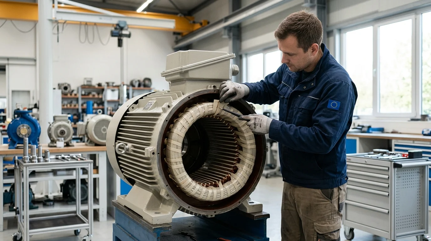
In heavy-duty European pump and compressor applications—ranging from municipal wastewater treatment plants to high-pressure chemical processing facilities—the reliability of electric motors is fundamentally tied to the integrity of their coil insulation systems. Continuous operation in these demanding industrial environments exposes motors to severe operational stresses, inevitably leading to insulation degradation over time.
Proactive coil insulation system upgrades offer a strategic method to extend motor life and improve overall system resilience. By utilizing advanced materials and modern winding techniques, facility operators can enhance the durability of aging motor assets, ensuring continuous fluid and gas processing.
Key Electrical, Thermal, and Mechanical Stressors
Electric motors in industrial pumps and compressors face a continuous barrage of electrical, thermal, and mechanical stressors. Thermal aging remains the primary catalyst for insulation failure, often exacerbated by restricted ambient airflow, continuous high-load operation, or frequent start-stop cycles. In demanding European industrial environments, operating temperatures frequently exceed 130°C, accelerating the chemical breakdown of standard insulation materials.
Simultaneously, mechanical vibrations from reciprocating compressor cycles and voltage spikes from power supply fluctuations inflict physical and electrical wear. Voltage transients can peak at 2.5 to 3.0 times the nominal voltage, creating localized micro-tears in the insulation layer. Over time, these combined stressors compromise the dielectric strength of the coils, leading to inter-turn short circuits, ground faults, and ultimately complete motor failure.
How to Define an Insulation System Upgrade
An insulation system upgrade is not merely a standard rewind; it involves completely replacing the existing insulation architecture with superior, higher-rated materials. This comprehensive process redefines the thermal and electrical boundaries of the motor, ensuring it can withstand operational extremes that would rapidly degrade the original factory configuration.
A standard upgrade often involves transitioning from a conventional Class B (130°C) or Class F (155°C) system to a highly robust Class H (180°C) or even Class N (200°C) architecture. According to the Arrhenius equation applied to electrical insulation aging, thermal life expectancy roughly doubles for every 10°C reduction in operating temperature relative to the insulation’s maximum thermal limit. However, this rule applies primarily to specific insulation systems under controlled conditions; actual longevity depends heavily on temperature distribution, hotspot factors, and measurement uncertainty. Nevertheless, upgrading the insulation class provides a significant, quantifiable buffer against thermal overloads, reducing the probability of premature failure.
Specifications and Materials to Compare
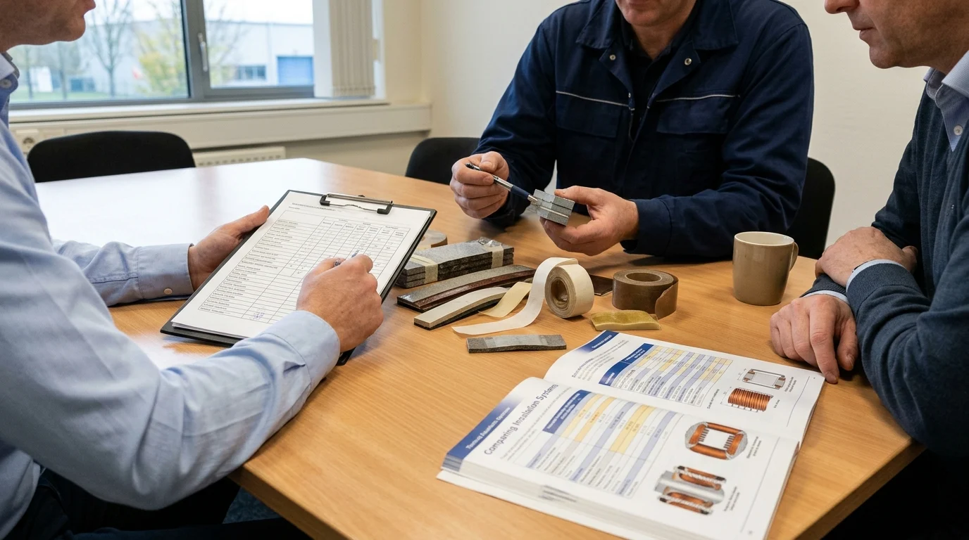
Selecting the correct materials and engineering specifications is critical when designing a coil insulation upgrade. The primary objective is to match the thermal, chemical, and electrical resistance of the new insulation system to the specific environmental hazards and duty cycles of the pump or compressor application.
Thermal Class, Resin, and Conductor Requirements
The foundation of an upgraded insulation system relies on the engineered synergy between the thermal class rating, the impregnating resin, and the primary conductor insulation. Modern European motor upgrades heavily favor vacuum pressure impregnation (VPI) using 100% solid epoxy resins over traditional dip-and-bake polyester varnishes. The VPI process eliminates microscopic air voids within the coil, while epoxy provides superior mechanical rigidity and chemical resistance—vital characteristics for pumps handling corrosive fluids or operating in high-humidity zones.
To illustrate the differences in thermal capabilities, the following table compares common insulation classes utilized in European motor upgrades:
| Thermal Class | Max Continuous Temperature (°C) | Typical Application Profile |
|---|---|---|
| Class B | 130°C | Legacy standard duty centrifugal pumps |
| Class F | 155°C | Modern standard industrial compressors |
| Class H | 180°C | Heavy-duty, high-ambient process operations |
| Class N | 200°C | Extreme industrial environments, submersible borehole pumps |
Beyond the resin, upgrading the conductor itself often involves utilizing advanced mica-taped copper wire. Mica offers exceptional dielectric strength and forms a resilient barrier that prevents turn-to-turn shorts even under severe, sustained thermal stress.
IEC Standards and Variable-Frequency Drive Considerations
European industrial facilities increasingly rely on Variable-Frequency Drives (VFDs) to optimize the energy consumption and flow rates of pumps and compressors. However, VFDs introduce damaging high-frequency voltage pulses. Therefore, modern upgrades must rigorously comply with stringent technical standards, notably IEC 60034-18-41, which governs the tests that qualify partial discharge-free insulation systems for rotating machines.
VFD-induced voltage rise times (dV/dt) can easily exceed 1,000 V/µs, generating localized partial discharges that rapidly erode standard enamel wire coatings. To combat this electrical stress, an upgraded system must incorporate specialized corona-resistant magnet wire and enhanced phase-to-phase insulation materials. By strictly adhering to these IEC standards, the upgraded motor is electromagnetically shielded against the rapid voltage spikes and harmonic distortions inherent to modern inverter-duty applications.
How to Plan an Upgrade
Executing a successful insulation upgrade requires meticulous logistical and financial planning. Facility managers must carefully balance the immediate upfront costs of motor removal and external refurbishment against the long-term operational benefits of extended lifecycle reliability and enhanced process stability.
A Practical Process to Reduce Downtime
To minimize production disruption, operators should strategically integrate insulation upgrades into scheduled predictive maintenance programs, rather than treating them as reactive emergency repairs. Advanced condition monitoring tools, such as high-voltage surge testing, polarization index (PI) measurements, and routine thermography, accurately identify degrading insulation months before an in-service failure occurs.
Once condition monitoring identifies a degrading motor, operators must secure a highly qualified electromechanical service center capable of executing the upgrade. Lead times for custom coil manufacturing, comprehensive VPI processing, and precision rewinding typically range from 3 to 6 weeks. Proper scheduling during planned plant turnarounds is essential to avoid significant unplanned downtime costs, which are often estimated in the tens of thousands of euros per day in critical European continuous-process facilities such as petrochemical refineries or municipal water treatment plants.
When to Upgrade, Rewind, or Replace
Determining the optimal path between upgrading, performing a standard rewind, or purchasing a completely new motor depends on several technical and economic thresholds.
Key Takeaways
- Assess thermal load, vibration, start-stop frequency, and voltage quality before specifying any coil insulation upgrade.
- Consider upgrading aging Class B or Class F motors to Class H or Class N insulation when operating temperatures approach or exceed 130°C.
- Use vacuum pressure impregnation with 100% solid epoxy where pumps or compressors face continuous duty, vibration, moisture, or chemical exposure.
- Treat voltage spikes of 2.5 to 3.0 times nominal voltage as a serious insulation-risk factor requiring stronger dielectric protection.
- Do not rely on thermal class alone; validate cooling, hotspot distribution, resin compatibility, and conductor insulation for the specific application.
Frequently Asked Questions
Why do pump and compressor motors need better coil insulation?
They often run continuously under heat, vibration, moisture, load cycling, and voltage spikes. These stresses reduce dielectric strength and can lead to inter-turn shorts, ground faults, and unplanned motor failure.
How is an insulation upgrade different from a standard rewind?
A standard rewind restores the original design. An upgrade replaces the insulation architecture with higher-rated materials, improved resins, and modern winding methods to increase thermal, electrical, and mechanical resilience.
Which insulation classes are commonly used for upgrades?
Many upgrades move motors from Class B at 130°C or Class F at 155°C to Class H at 180°C, or in harsher duties, Class N at 200°C.
How do voltage transients damage motor coils?
Voltage spikes can reach 2.5 to 3.0 times nominal voltage, stressing the insulation and creating localized defects. Over time, these defects can develop into partial discharge, shorts, or ground faults.
Why is VPI epoxy often preferred over dip-and-bake varnish?
Vacuum pressure impregnation with 100% solid epoxy provides deeper penetration, stronger bonding, better void reduction, and improved resistance to heat, vibration, and contamination in demanding industrial service.
Post time: Jun-29-2026