
Introduction
In precision measurement systems, a switching solenoid can turn a routine control function into a source of fast transients, conducted noise, and radiated emissions that upset low-level signals and threaten EMC compliance in Europe. The challenge is especially acute in instruments that combine inductive actuators with sensitive analog front ends, high-resolution converters, or tightly packed electronics. This article explains where solenoid-generated EMI comes from, why it matters under European compliance requirements, and which design choices most effectively reduce it. You will learn how suppression components, wiring layout, grounding, shielding, and switching strategy work together to lower interference without compromising actuator performance.
Why Reduce EMI from Solenoid Coils
Electromagnetic interference (EMI) presents a significant challenge for engineers designing precision measurement equipment for the European market. Solenoid coils, frequently used in pneumatic and fluid control systems within these devices, are notorious sources of electrical noise. Under the European EMC Directive 2014/30/EU, laboratory and measurement equipment must adhere to strict immunity and emissions standards to obtain the mandatory CE marking. Failure to manage solenoid-induced EMI jeopardizes CE compliance—risking costly product recalls—and compromises the fundamental accuracy of sensitive instruments.
How solenoid coils generate EMI
Solenoid coils operate as inductive loads. During normal operation, current flows through the coil, generating a magnetic field to move an armature. The primary source of EMI occurs during de-energization. When the power supply is abruptly cut, the magnetic field rapidly collapses, inducing a high-voltage transient known as inductive kickback or flyback voltage. The magnitude of this spike is governed by the rate of current change (di/dt); faster-switching relays produce exponentially larger transients.
Without suppression, a standard 24V DC solenoid coil can generate a reverse voltage spike exceeding 300V to 1000V in microseconds. This high-frequency transient propagates through power lines as conducted emissions and radiates through the air as broadband electromagnetic noise, disrupting nearby circuitry.
When EMI becomes a critical issue
EMI crosses the threshold from a minor nuisance to a critical failure point in sensitive measurement environments. European standards, such as EN 61326-1 for laboratory and measurement equipment, mandate high immunity levels. However, internal EMI from unsuppressed solenoids can easily couple into adjacent analog signal paths.
In applications like coordinate measuring machines, spectrometers, or precision analytical balances, sensor signals often operate in the millivolt (mV) or microvolt (µV) range. A stray transient of even 50 mV coupling into a sensor trace can cause data corruption, false triggers, or permanent degradation of delicate microprocessors. In these high-precision contexts, resolving EMI is not merely a compliance checkbox but a core functional requirement.
How to Reduce EMI from Solenoid Coils
Mitigating electromagnetic interference from solenoid coils requires a dual-pronged approach. Engineers must implement component-level design measures to suppress the transient voltage at the source, alongside rigorous system-level installation practices to prevent residual noise from coupling into sensitive measurement circuits.
Design measures that lower EMI
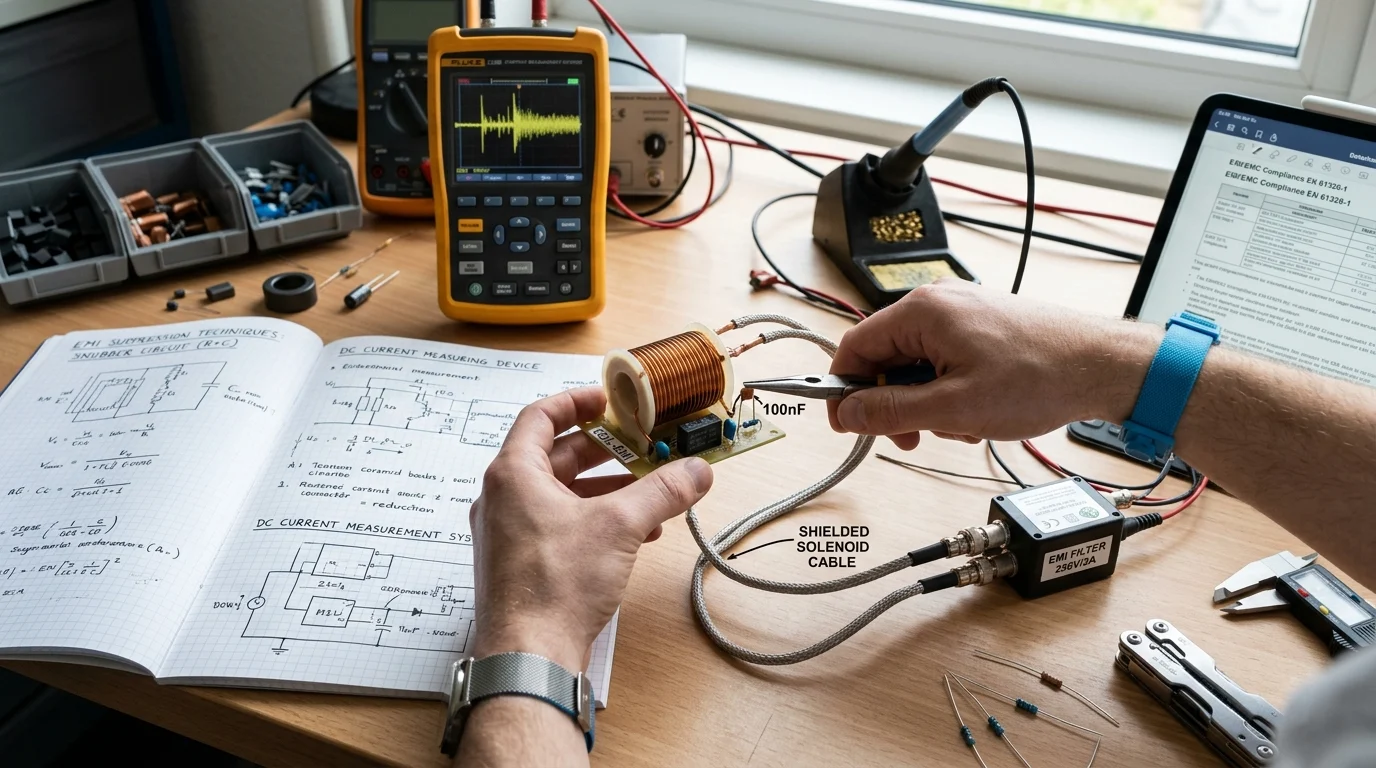
The most effective way to lower EMI is to integrate suppression components directly across the solenoid coil. Flyback diodes are a common choice for DC coils, routing the inductive current back through the coil to dissipate harmlessly. However, simple diodes can increase the drop-out time of the valve. For faster response times, Zener diode combinations or Metal Oxide Varistors (MOVs) are preferred. In AC applications, RC snubber circuits—typically utilizing a 100-ohm resistor in series with a 0.1 µF capacitor—are highly effective at dampening high-frequency oscillations.
| Suppression Method | Best Application | EMI Reduction Effectiveness | Impact on Valve Drop-out Time |
|---|---|---|---|
| Standard Flyback Diode | Basic DC Coils | High (eliminates voltage spike) | Significantly increases delay |
| Diode + Zener Diode | Fast-acting DC Valves | High | Minimal delay |
| RC Snubber (100Ω + 0.1µF) | AC Solenoid Coils | Moderate to High | Negligible |
| Metal Oxide Varistor (MOV) | AC/DC General Use | Moderate (clips overvoltage) | Negligible |
Installation and operating practices
Even with proper coil design, physical installation practices are vital for minimizing EMI spread. Cable routing plays a critical role; power cables driving the solenoid coils should be physically separated from sensitive sensor lines by a minimum distance of 20 centimeters. When cables must cross, they should do so at a 90-degree angle to minimize inductive coupling.
Furthermore, utilizing shielded, twisted-pair cables for the solenoid power supply helps cancel out radiated magnetic fields. Grounding the cable shield at a single point prevents the formation of ground loops, which can otherwise act as antennas for electromagnetic noise. Adding clamp-on ferrite beads to the solenoid power cables near the source can further attenuate high-frequency noise above 10 MHz, providing an extra layer of protection for nearby European-certified instrumentation.
How to Validate and Specify Low-EMI Solenoid Coils

Designing a low-EMI system is only half the battle; ensuring consistent compliance across production volumes requires rigorous validation and strategic procurement. Engineers must define clear acceptance criteria and partner with suppliers capable of delivering high-quality, fully documented solenoid coils to avoid costly lifecycle redesigns.
Test methods and acceptance criteria
Validation testing must align with European standards, specifically CISPR 11 (EN 55011) for industrial, scientific, and medical (ISM) equipment. Testing involves measuring both conducted emissions on the power lines using a Line Impedance Stabilization Network (LISN) and radiated emissions in a certified anechoic chamber.
For Class A measurement equipment, radiated emissions must typically remain below 40 dBµV/m at a measurement distance of 10 meters for frequencies between 30 MHz and 230 MHz. Acceptance criteria should explicitly require transient immunity testing, such as IEC 61000-4-4 for electrical fast transients (EFT), to ensure the solenoid’s switching operation does not disrupt adjacent microcontrollers or violate the CE marking baseline.
Supplier selection and specification
Specifying low-EMI components requires selecting a manufacturing partner with a robust quality management system and specialized engineering capabilities. Companies like Ningbo Feiniu Electronic Technology Co., Ltd., which focus on the research and manufacturing of precision parts, offer comprehensive portfolios including solenoid valves, electromagnet coils, and pulse control instruments. Engaging with such specialized suppliers ensures access to components designed with EMI mitigation in mind.
When drafting specifications, buyers should mandate ISO 9001 certification and demand strict quality control metrics, such as a defect rate below 50 Parts Per Million (PPM). Additionally, establishing clear logistical parameters—such as a Minimum Order Quantity (MOQ) of 500 to 1,000 units for custom-suppressed coils and defining lead times of 4 to 6 weeks—ensures a stable, compliant supply chain for the mass production of European measurement equipment.
Key Takeaways
- The most important conclusions and rationale for How to Reduce Electromagnetic Interference (EMI) from Solenoid Coils in Sensitive European Measurement Equipment
- Specs, compliance, and risk checks worth validating before you commit
- Practical next steps and caveats readers can apply immediately
Frequently Asked Questions
Why do solenoid coils create EMI in sensitive measurement equipment?
When a coil is switched off, its magnetic field collapses and creates a fast flyback voltage spike. That transient can travel on power lines or radiate into nearby low-level sensor circuits.
Which suppression method is best for a 24V DC solenoid coil?
A flyback diode is the simplest option, but it slows valve release. If fast drop-out matters, use a diode plus Zener to clamp voltage while keeping response time tighter.
What should I use for AC solenoid coils to reduce EMI?
An RC snubber is a common choice. A typical starting point is 100 ohms in series with 0.1 µF across the coil, then verify performance in your actual circuit.
How should solenoid and sensor cables be routed to limit interference?
Keep solenoid power cables at least 20 cm away from sensitive sensor lines. If they must cross, do it at 90 degrees, and prefer shielded twisted-pair cable for the coil supply.
How can I support CE compliance for European measurement equipment?
Control EMI at the coil, apply good cable shielding and grounding, and validate the final assembly against EN 61326-1 under the EMC Directive 2014/30/EU before CE marking.
Post time: May-14-2026