
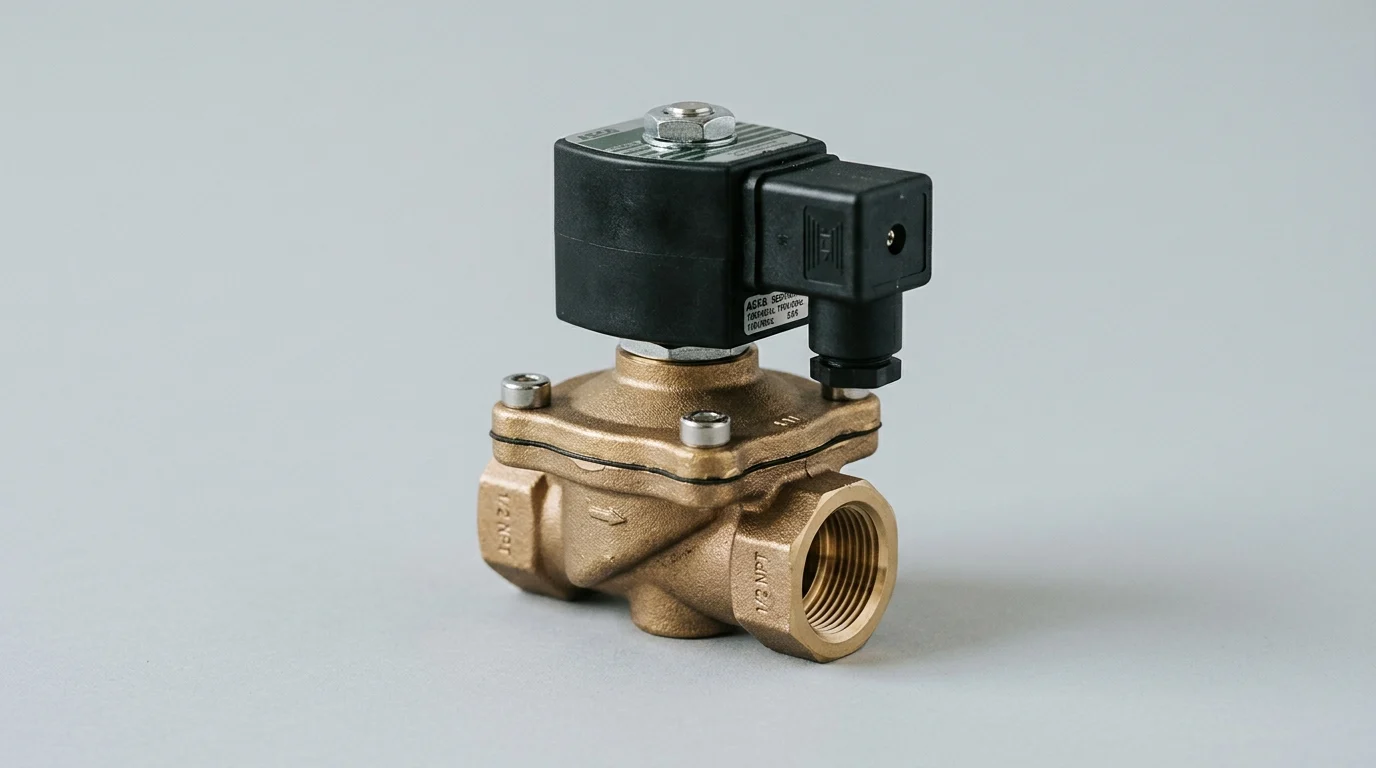
A single failed solenoid valve can stop a production line, spoil material, damage downstream equipment, or trigger a compliance event. In high-throughput manufacturing and process environments, that risk is not theoretical—unplanned outages can cost more than $10,000 per hour. The difference between a minor maintenance task and a major shutdown is often a documented, risk-based schedule that accounts for cycle rate, pressure, media compatibility, heat, contamination, and electrical stress. This guide explains how to identify the valves that deserve proactive attention, recognize the failure modes that matter most, and structure daily, periodic, and annual tasks so maintenance teams can reduce downtime without over-servicing low-risk assets.
Why Solenoid Valve Preventive Maintenance Prevents Downtime
In continuous process industries, solenoid valves act as the final control elements for critical fluid and gas routing. When these components fail unexpectedly, the resulting process interruptions generate severe financial penalties. Beyond immediate production losses, sudden valve malfunctions can lead to material spoilage, environmental non-compliance, and secondary equipment damage.
Industry data indicates that unexpected outages in automated manufacturing and petrochemical processing frequently exceed $10,000 per hour. Implementing a rigorous upkeep schedule specific to these assets is essential for mitigating these risks, ensuring system reliability, and maintaining strict process safety standards. However, it is important to note an early caveat: low-cost, non-critical disposable solenoid valves may not merit scheduled servicing at all, as their replacement cost is often lower than the labor required for even minimal maintenance.
Critical solenoid valve failure modes
Solenoid valves typically fail through three primary mechanisms: electrical coil burnout, mechanical armature sticking, and elastomeric seal degradation. Coil burnout often results from sustained overvoltage or a jammed armature that prevents the magnetic circuit from closing, causing prolonged inrush current. Thermal degradation is highly predictable; for example, operating a Class H insulated coil (rated for 180°C) beyond its thermal limit reduces its expected operational lifespan by 50% for every 10°C of excess heat.
Meanwhile, armature sticking is frequently caused by particulate accumulation in the core tube. Seal degradation stems from chemical incompatibility or abrasive media wearing down the FKM, EPDM, or NBR components, eventually leading to internal bypass leakage or external fluid weeping.
Operating conditions that increase failure risk
The operational environment directly dictates the baseline risk of premature valve failure. High-cycle applications subject internal springs and dampening rings to accelerated mechanical fatigue, while extreme pressure fluctuations can stretch or rupture flexible diaphragms. Operating a valve continuously at greater than 80% of its Maximum Operating Pressure Differential (MOPD) significantly accelerates wear on internal guiding surfaces and dynamic seals.
Furthermore, ambient conditions such as high humidity, corrosive atmospheres, or excessive plant vibration compromise the IP-rated electrical enclosures. This allows moisture ingress that degrades coil insulation and precipitates catastrophic short circuits, transforming a minor environmental challenge into a major system outage.
How to Build an Effective Maintenance Schedule
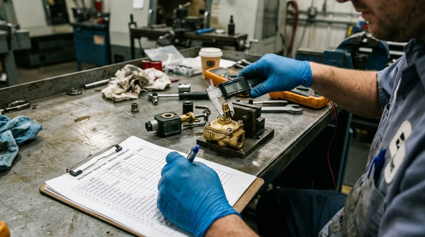
Transitioning from reactive firefighting to a structured reliability program requires a systematic approach to valve care. An effective schedule dictates specific interventions at daily, monthly, and annual intervals, aligning servicing activities with the operational demands placed on the fluid control system.
Documenting these intervals in a Computerized Maintenance Management System (CMMS) ensures technician accountability and provides a historical database for future lifecycle analysis.
Inspection, cleaning, and testing tasks
A comprehensive maintenance protocol encompasses visual, electrical, and mechanical assessments. Before initiating any cleaning or rebuild tasks, technicians must strictly adhere to lock-out/tag-out (LOTO) procedures, explicitly verifying a zero energy state—meaning the system is completely electrically de-energized and fully depressurized—to eliminate the hazards of servicing live lines. Routine visual inspections should verify the integrity of electrical connections and check for external fluid weeping at the valve body joints.
Maintenance protocols must explicitly separate direct-acting and pilot-operated valves, as their inspection and cleaning requirements differ materially. For direct-acting valves, cleaning focuses on flushing the valve body to remove scale and particulate buildup from the core tube and armature assembly. For pilot-operated models, technicians must also meticulously clear the pilot ports and bleed orifices to prevent sluggish actuation.
Electrical testing is equally critical for predicting failure. Technicians must routinely measure the coil’s electrical resistance using a calibrated multimeter. A resistance variance of ±5% from the manufacturer’s specified baseline can indicate impending electrical degradation, but these measurements must be temperature-compensated. Because copper winding resistance changes roughly 0.4% per °C, failing to adjust for temperature may lead technicians to scrap healthy coils.
Time-based vs condition-based maintenance
Maintenance schedules traditionally rely on calendar-based intervals, but modern facilities increasingly adopt condition-based methodologies. Time-based maintenance might dictate rebuilding a valve every 12 months, regardless of its actual wear, which guarantees baseline reliability but incurs unnecessary labor and parts costs. Conversely, condition-based maintenance utilizes acoustic emission sensors and continuous current monitoring to detect internal leakage or sluggish armature movement in real-time.
Shifting from rigid calendar replacements to condition-based monitoring can significantly extend the active service life of industrial solenoid valves. While some facilities report service-life extensions of 30% to 40%, actual results vary widely depending on the specific application, fluid media, and operating environment.
| Maintenance Strategy | Primary Trigger | Cost Profile | Best Applied To |
|---|---|---|---|
| Time-Based (Preventive) | Calendar intervals or cycle counts | Moderate initial setup, higher ongoing parts cost | Standard utility valves, predictable wear environments |
| Condition-Based (Predictive) | Real-time sensor data (acoustics, current) | High initial sensor investment, lower lifecycle cost | Critical process loops, highly variable operating conditions |
How to Measure and Improve Maintenance Results
To justify the ongoing investment in an asset reliability program, facility managers must track specific performance data. Relying on anecdotal evidence of improved uptime is insufficient for modern industrial operations.
Quantifying the impact of these activities ensures continuous improvement and optimizes the allocation of technical resources across the plant floor. Facilities should establish a rigid baseline with tiered benchmarks: target 99.5% to 99.9% availability for critical single points of failure, while reserving a 98% target for redundant or non-critical utility loops. Because 98% annual availability implies over seven days of acceptable downtime, applying it to highly critical processes without redundancy is a significant operational risk.
KPIs that confirm reduced unplanned downtime
The effectiveness of a servicing schedule is validated through specific Key Performance Indicators (KPIs). Mean Time Between Failures (MTBF) is the most critical metric for evaluating solenoid valve reliability. A successfully implemented proactive strategy should substantially increase the MTBF of standard industrial solenoid valves, pushing them well beyond their reactive baselines—though exact hour extensions will vary widely by application.
Additionally, tracking Mean Time To Repair (MTTR) highlights the efficiency of the maintenance
Key Takeaways
- Prioritize preventive maintenance for critical solenoid valves because unexpected outages in automated manufacturing and petrochemical operations can exceed $10,000 per hour.
- Track valve inspections, tests, rebuilds, and failures in a CMMS to create accountability and improve lifecycle decisions over time.
- Investigate high-risk conditions such as dirty media, corrosive atmospheres, vibration, humidity, high cycle rates, and operation above 80% of MOPD.
- Before cleaning or rebuilding any valve, use lock-out/tag-out and confirm the system is electrically de-energized and fully depressurized.
- Treat low-cost, non-critical disposable solenoid valves differently, since replacement may be more economical than scheduled maintenance.
- Monitor coil temperature and voltage closely, as overheating beyond insulation limits can reduce expected coil life by 50% for every 10°C increase.
Frequently Asked Questions
How often should solenoid valves be inspected?
Critical valves should follow a documented schedule with frequent visual checks, periodic electrical testing, and annual functional review. Exact intervals depend on cycle rate, media cleanliness, pressure, temperature, vibration, and failure consequence.
What are the most common solenoid valve failure modes?
The main failure modes are coil burnout, armature sticking, and seal degradation. These are commonly caused by overheating, voltage issues, particulate contamination, chemical incompatibility, abrasive media, or excessive pressure differential.
When is preventive maintenance not worth doing?
For low-cost, non-critical disposable solenoid valves, scheduled servicing may cost more than replacement. In those cases, keeping spares on hand and replacing on failure can be more economical.
Why should solenoid valve maintenance be tracked in a CMMS?
A CMMS creates accountability, schedules recurring tasks, records test results, and builds failure history. This data helps refine maintenance intervals and identify valves with abnormal wear or repeated downtime risk.
What safety steps are required before servicing a solenoid valve?
Technicians should follow lock-out/tag-out procedures and verify a zero-energy state. That means the valve circuit is electrically de-energized and the fluid system is fully depressurized before inspection, cleaning, or rebuild work begins.
Post time: Aug-20-2026