
A small electro-hydraulic valve can create a big uptime problem when it starts to respond slowly, stick, or lose electrical integrity. In CAT equipment, the 4582950 solenoid valve helps translate ECM commands into hydraulic action, so a fault can show up as sluggish implements, harsh shifts, weak braking, or intermittent diagnostic codes. The challenge is that those same complaints can also come from wiring, grounding, contamination, or pump-related issues. This guide explains the practical symptoms technicians should watch for, how to separate electrical faults from hydraulic problems, and when replacement is justified. The goal is simple: catch failure early, avoid unnecessary parts swaps, and keep the machine working before downtime becomes expensive.
How Solenoid Valve 4582950 Failure Symptoms Affect CAT Uptime
Unplanned downtime in heavy-duty Caterpillar machinery frequently traces back to electro-hydraulic control failures. The solenoid valve 4582950 operates as a critical junction between the electronic control module (ECM) and the hydraulic actuation system across various CAT machine families. When this valve begins to fail, operators experience cascading performance degradation that can halt operations entirely. Recognizing the symptoms early is paramount for technicians to safeguard fleet availability and prevent secondary component damage.
Note: Because compatibility, exact specifications, and fluid cleanliness requirements vary by CAT model, always confirm this valve applies to your specific equipment. All precise numerical figures provided below (e.g., resistance, response times, bypass rates) are illustrative example values only. Always verify your machine’s baseline specifications against the appropriate OEM service manual.
What CAT Solenoid Valve 4582950 Does
The 4582950 solenoid valve functions as a direct-acting, electrically operated directional control valve. Operating within CAT’s 24V DC electrical architecture, it translates ECM signals into precise hydraulic fluid routing. This component handles substantial hydraulic pressures, often operating within systems pressurized up to 3,500 psi (24 MPa). By regulating fluid flow to secondary hydraulic circuits, the valve controls specific machine functions depending on its placement. In implement circuits, it ensures synchronized movement of booms or buckets; in transmission circuits, it dictates precise gear shifting; and in engine-brake circuits, it manages reliable retardation. Maintaining an ISO 4406 fluid cleanliness level of at least 18/16/13 is generally recommended, as microscopic particulate matter can disrupt the tight tolerances between the internal spool and the valve body.
Early Failure Symptoms to Watch For
Technicians must monitor for subtle deviations in machine responsiveness. Symptoms vary based on the valve’s application: implement circuit failures manifest as sluggish reaction times or unpredictable hydraulic drift under load; transmission circuit failures cause erratic gear engagement or harsh shifting; and engine-brake circuit failures result in weak or delayed retardation. While a healthy 4582950 valve might actuate within an illustrative range of 30 to 50 milliseconds, internal wear, silting, or coil degradation can cause this response time to exceed 100 milliseconds, creating noticeable operational lag. Other distinct symptoms include localized overheating near the valve block, intermittent ECM fault codes related to open or short circuits, and audible buzzing from the solenoid coil. This buzzing frequently indicates inadequate magnetic field generation or a sticking armature attempting to overcome mechanical resistance.
How to Diagnose Solenoid Valve 4582950 Failure Symptoms
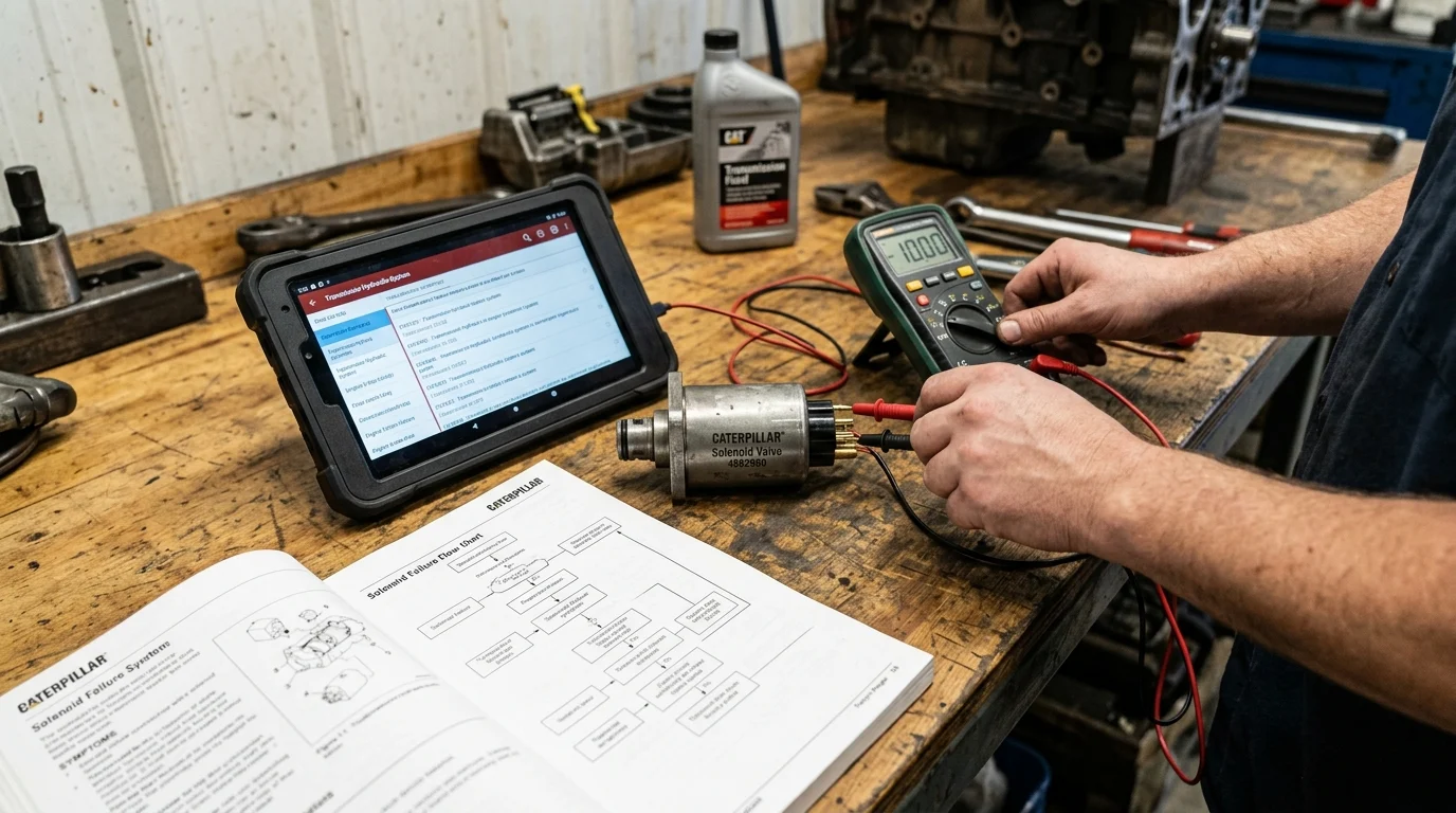
Accurate diagnosis of the 4582950 solenoid valve requires isolating the electrical control circuit from the mechanical hydraulic system. Technicians must avoid the common pitfall of immediately replacing the valve based solely on operator complaints, as wiring harness degradation, poor grounding, or upstream hydraulic pump issues can closely mimic solenoid failure. A systematic diagnostic protocol utilizing calibrated multimeters and high-pressure gauges ensures that maintenance efforts target the true root cause, minimizing unnecessary parts expenditure and preventing repeat failures. Before initiating any diagnostic procedures, technicians must ensure the equipment is properly locked out and tagged out (LOTO), and that all residual hydraulic pressure has been safely relieved to atmospheric pressure and a zero energy state is achieved.
Electrical and Hydraulic Checks
Diagnostic procedures begin with electrical verification using a digital multimeter. As an illustrative example, the 4582950 solenoid coil might present a resistance falling between 28 and 32 ohms at a standardized ambient temperature of 20°C (68°F). Because field conditions rarely match this baseline, coil resistance readings must be temperature-compensated to ensure an accurate diagnosis. Readings dropping significantly below the specified range indicate an internal short circuit, while an infinite reading (OL) confirms a broken winding or open circuit. Technicians must also verify that the ECM is delivering the correct pulse-width modulated (PWM) signal or steady 24V DC supply to the harness connector under actual load conditions. Once electrical integrity is confirmed, hydraulic diagnostics involve teeing a pressure gauge into the designated test port downstream of the valve. The system should reach target actuation pressure immediately upon solenoid energization; a pressure drop exceeding 10% of the baseline specification suggests internal fluid bypassing or severe spool wear.
Comparing Symptoms with Test Results
Correlating operational symptoms with hard diagnostic data prevents costly misdiagnosis. By structuring the diagnostic approach to evaluate both domains simultaneously, technicians can pinpoint whether the failure likely lies within the electrical generation of the magnetic field or the mechanical shifting of the hydraulic spool.
| Observed Symptom | Electrical Test Result | Hydraulic Test Result | Likely Diagnostic Conclusion | Secondary Check |
|---|---|---|---|---|
| Total loss of function | Infinite Ohms (Open) | Zero pressure at port | Burned solenoid coil; replace valve assembly | Verify ECM output and main relays |
| Sluggish operation | Normal (e.g., 28-32 Ohms)* | Slow pressure build-up | Sticking spool or internal fluid contamination | Inspect hydraulic filters and fluid condition |
| Intermittent stalling | Fluctuating supply voltage | Erratic gauge needle fluctuations | Wiring harness chafing or connector failure | Check ground straps and ECM harness pins |
| Overheating coil | Below spec (Short) | Failure to reach target pressure or pressure decay under sustained hold | Internal coil short circuit; replace valve | Confirm ambient cooling and system voltage |
*Illustrative example value only.
When to Replace Solenoid Valve 4582950
Determining the exact moment to retire the 4582950 solenoid valve depends on a combination of operational hours, diagnostic data, and the severity of the observed symptoms. While some legacy hydraulic components permit extensive rebuilding and machining, modern electro-hydraulic solenoids operate under such strict tolerances that they often demand outright replacement to guarantee system reliability and safeguard downstream components from catastrophic contamination. Maintaining critical spares like the 4582950 in inventory is a standard practice, ensuring that when diagnostics confirm a failure, the asset can be returned to service within the same shift.
Repair vs Replacement Criteria
The industry standard lifecycle for a high-cycle CAT solenoid valve often ranges from 8,000
Key Takeaways
- Confirm that valve 4582950 is correct for the specific CAT model before ordering or installing a replacement.
- Treat sluggish implements, harsh shifting, weak retardation, buzzing, overheating, and intermittent ECM codes as early warning signs that require prompt testing.
- Diagnose the electrical circuit first by checking supply voltage, coil condition, continuity, connector integrity, and grounding before condemning the valve.
- Verify hydraulic pressure, flow, and contamination levels because pump issues or dirty oil can create symptoms that resemble solenoid failure.
- Use OEM service data for exact resistance, response-time, pressure, and cleanliness requirements because example values may not apply to every machine.
- Replace the valve only after testing confirms internal sticking, coil failure, leakage, or delayed actuation and external causes have been eliminated.
Frequently Asked Questions
What does the CAT 4582950 solenoid valve control?
It converts ECM electrical commands into hydraulic flow control. Depending on its location, it may affect implement movement, transmission shifting, engine braking, or another secondary hydraulic function.
What are the most common symptoms of a failing 4582950 solenoid valve?
Watch for sluggish hydraulic response, erratic shifting, weak engine braking, hydraulic drift, intermittent fault codes, buzzing from the coil, or localized overheating near the valve block.
Can wiring problems mimic solenoid valve failure?
Yes. Damaged harnesses, poor grounds, corroded connectors, or ECM signal issues can look like a bad solenoid. Electrical checks should be completed before replacing the valve.
How should technicians diagnose the 4582950 valve before replacement?
Start by separating electrical and hydraulic causes. Use a calibrated multimeter to check voltage, resistance, continuity, and grounding, then verify hydraulic pressure and flow with proper gauges.
When should the 4582950 solenoid valve be replaced?
Replace it when testing confirms coil failure, internal sticking, delayed actuation, overheating, leakage, or repeated fault codes after wiring, ECM commands, and hydraulic supply issues have been ruled out.
https://flyingbull.en.made-in-china.com/product/baiYIARlFxhn/China-458-2950-Solenoid-Valve-for-Loader-Proportional-Solenoid-Valve-Construction-Machinery-Accessories-4582950.html
Post time: Aug-17-2026