
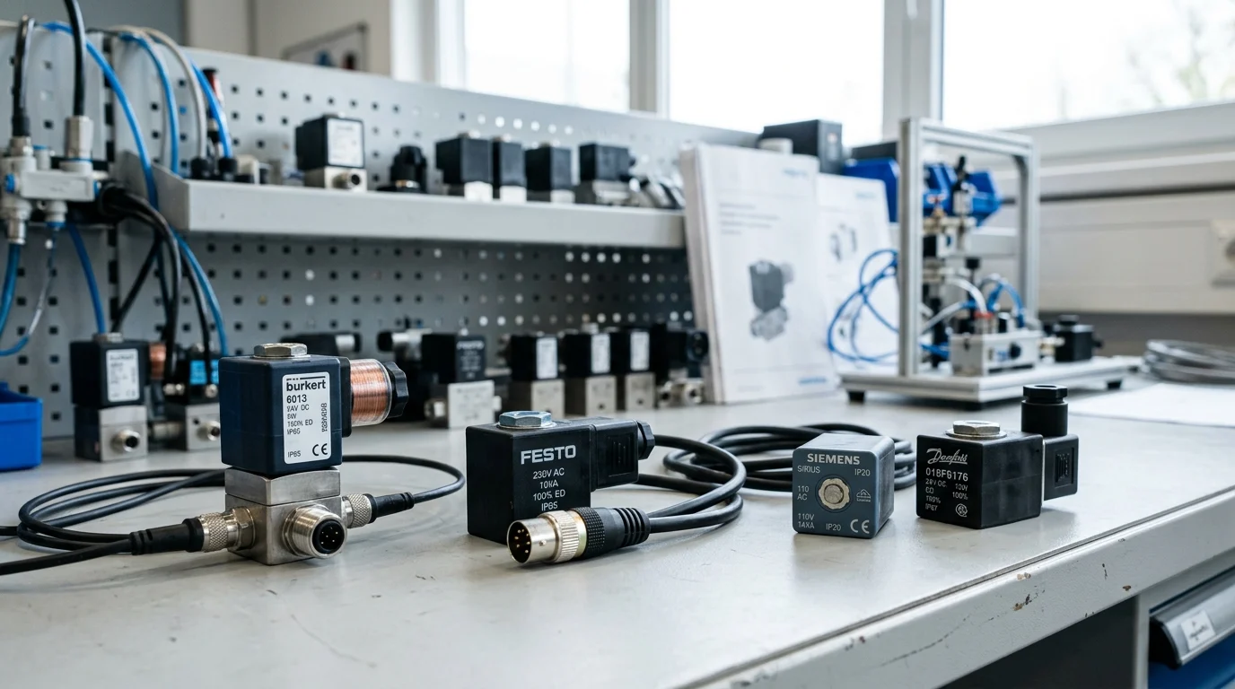
A solenoid valve coil may look like a small accessory, but in automated fluid control it often decides whether a line runs smoothly or stops without warning. For European engineers working with pneumatic and hydraulic circuits, coil selection is not just a voltage choice; it affects response time, heat rise, PLC compatibility, safety compliance, and enclosure protection. This guide explains the practical meaning of voltage, power consumption, duty cycle, temperature limits, and IP rating, with attention to typical industrial values such as 24V DC control, 2W–8W pilot coils, and ATEX temperature constraints. The goal is simple: specify coils that actuate reliably, survive their environment, and support compliant machine design.
Strategic Role of Solenoid Valve Coils in European Automation
Solenoid valve coils act as the critical electromechanical interface within fluid control systems across European manufacturing, chemical processing, and packaging automation. Their primary function—converting electrical energy into linear magnetic force to actuate a valve armature—determines the responsiveness and efficiency of the entire pneumatic or hydraulic circuit. In highly integrated automation environments, the reliability of these inductive components directly dictates overall system availability and throughput.
Key coil specifications that influence performance
The operational efficacy of a solenoid coil hinges on its specific electrical and mechanical parameters. Resistance, inductance, and power consumption dictate the magnetic flux density generated upon energization. For instance, standard industrial coils often operate within a power consumption band of 2W to 8W for pilot-operated valves, whereas direct-acting valves may demand 15W to 30W to overcome high fluid pressures. A typical 24V DC coil with a 5W power rating will exhibit a resistance of approximately 115 ohms. The physical winding density and wire insulation class determine the component’s ability to sustain this magnetic force without succumbing to thermal degradation under continuous electrical load.
Impact on uptime, safety, and compliance
Coil failure is a leading cause of unplanned downtime in fluid automation. A compromised coil can lead to sluggish valve actuation or complete failure to shift, jeopardizing both process integrity and machine safety. In the European market, adherence to stringent regulatory frameworks is mandatory. Coils deployed in potentially explosive atmospheres must comply with the ATEX Directive (2014/34/EU), often requiring encapsulated designs and strict temperature classifications, such as a T4 rating that limits maximum surface temperatures to 135°C. Furthermore, compliance with the Low Voltage Directive (LVD) and Electromagnetic Compatibility (EMC) Directive ensures that the coil neither emits nor is susceptible to electromagnetic interference, safeguarding sensitive local PLCs and factory sensing equipment.
Comparing Solenoid Valve Coil Options
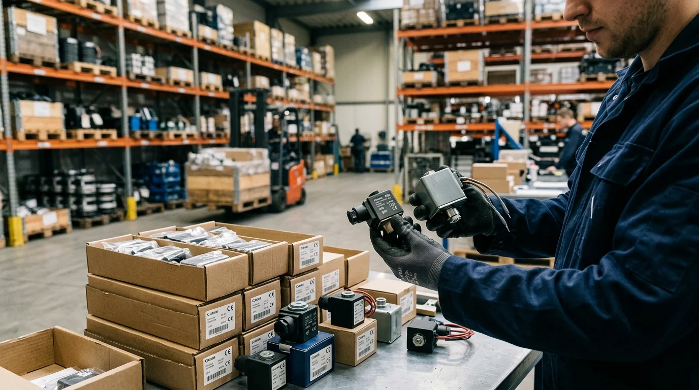
Specifying the correct solenoid coil requires a rigorous comparative analysis of electrical characteristics and environmental resilience. Automation engineers must balance the dynamic response requirements of the fluid application against the available control architecture, power supply stability, and ambient operating conditions.
AC versus DC coil selection
The fundamental choice between Alternating Current (AC) and Direct Current (DC) coils dictates the electrical behavior and mechanical wear of the valve assembly. AC coils draw a high inrush current—often 2 to 3 times the steady-state holding current—resulting in rapid actuation times typically ranging from 5 to 20 milliseconds. However, if the armature fails to seat completely due to particulate debris, the sustained inrush current will cause the coil to rapidly overheat and burn out. Conversely, DC coils exhibit a constant current draw determined purely by their ohmic resistance, making them structurally immune to inrush-related burnout. While DC coils actuate more slowly, typically requiring 30 to 50 milliseconds, their seamless integration with modern 24V DC PLC outputs makes them the dominant standard for contemporary European automation systems.
Voltage, duty cycle, temperature, and IP rating
Beyond the AC/DC dichotomy, engineers must evaluate duty cycle, thermal limits, and environmental protection. A 100% duty cycle (Continuous Duty) rating is essential for valves that remain energized indefinitely without exceeding thermal thresholds. Insulation class dictates the maximum allowable operating temperature; Class F is rated for up to 155°C, while Class H withstands up to 180°C. Ingress Protection (IP) ratings define the coil’s defense against particulate and moisture ingress. Standard industrial environments typically require IP65 for protection against low-pressure water jets, whereas marine or hygienic applications demand IP67 for temporary submersion or IP69K for high-pressure, high-temperature washdowns.
| Specification | AC Coils (e.g., 230V AC) | DC Coils (e.g., 24V DC) |
|---|---|---|
| Inrush Current | High (2-3x holding current) | None (Constant current) |
| Actuation Speed | 5-20 ms (Fast) | 30-50 ms (Slower) |
| Burnout Risk | High if armature jams | Very low |
| Common Application | Legacy systems, high-speed switching | Modern PLC control, battery backup |
Selecting, Sourcing, and Validating Coils
Effective procurement and integration of solenoid valve coils demand a systematic approach to specification and lifecycle management. Engineers must bridge the gap between theoretical electrical requirements and practical, long-term operational realities on the factory floor.
Practical selection steps for engineers
The selection process initiates with mapping the control system’s output capabilities to the coil’s power requirements. Engineers must verify that the PLC or solid-state relay can supply the necessary wattage, particularly for high-power direct-acting valves requiring up to 30W, without exceeding channel current limits. Following electrical matching, the ambient operating environment must be assessed. If the installation is subject to heavy washdowns, specifying an IP67 or IP69K rated coil with an integrated DIN 43650 connector and molded cable is imperative. Validation should include dielectric withstand testing (Hipot) at 1000V to ensure insulation integrity before commissioning. Additionally, standardizing on a uniform voltage—predominantly 24V DC—simplifies inventory management and reduces the Minimum Order Quantity (MOQ) burdens when sourcing replacements from industrial distributors.
Lifecycle guidance for reliable operation
Maximizing the operational lifespan of a solenoid coil requires proactive thermal and electrical management. Voltage fluctuations must remain strictly within the standard tolerance of ±10% of the nominal rating; chronic overvoltage accelerates thermal degradation of the winding insulation, while undervoltage prevents the armature from fully seating, leading to erratic flow control. Routine maintenance protocols should incorporate thermal imaging to detect abnormal heat signatures indicative of impending failure, internal shorting, or mechanical jamming. Furthermore, utilizing transient voltage suppression (TVS) diodes or varistors across the coil terminals protects upstream control electronics from the high-voltage inductive flyback generated during de-energization, ensuring the reliability of the entire automated circuit over millions of operational cycles.
Key Takeaways
- Specify 24V DC coils for most modern European PLC-based systems to simplify control wiring and avoid AC inrush-related burnout risks.
- Check coil power against valve type, as pilot-operated valves may need only 2W to 8W while direct-acting valves can require 15W to 30W.
- Allow for AC inrush current of roughly 2 to 3 times holding current when sizing power supplies and diagnosing overheating failures.
- Match the coil duty cycle to the real energisation pattern, especially where valves remain powered continuously during production.
- Verify ATEX, LVD, EMC, temperature class, and IP requirements early when coils are used in hazardous, wet, dusty, or electrically sensitive environments.
Frequently Asked Questions
What voltage is most common for solenoid valve coils in European automation?
24V DC is the dominant choice because it integrates cleanly with modern PLC outputs, offers predictable current draw, and avoids AC inrush-related overheating risks.
How much power does a typical solenoid valve coil use?
Pilot-operated valve coils often use about 2W to 8W, while direct-acting valves may require 15W to 30W to generate enough force against higher pressures.
Why can AC solenoid coils burn out if a valve sticks?
AC coils draw high inrush current, often 2 to 3 times holding current. If debris prevents the armature from seating, that inrush can continue and overheat the coil.
What does duty cycle mean for a solenoid coil?
Duty cycle defines how long a coil can remain energised without exceeding its thermal limits. Continuous-duty coils are designed for sustained operation; intermittent-duty coils need off-time to cool.
What IP rating should engineers consider for solenoid valve coils?
Select the IP rating based on exposure to dust, water, washdown, or outdoor conditions. Higher IP ratings improve enclosure protection but must still match connector and installation quality.
Post time: Sep-19-2026