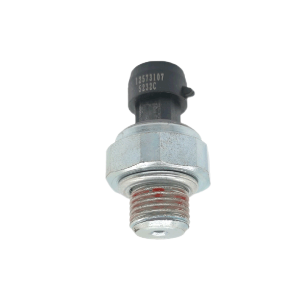
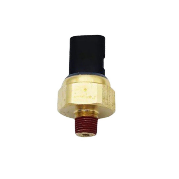
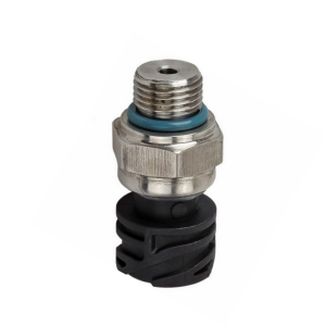
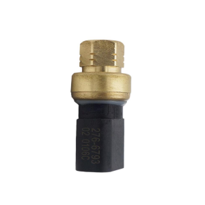
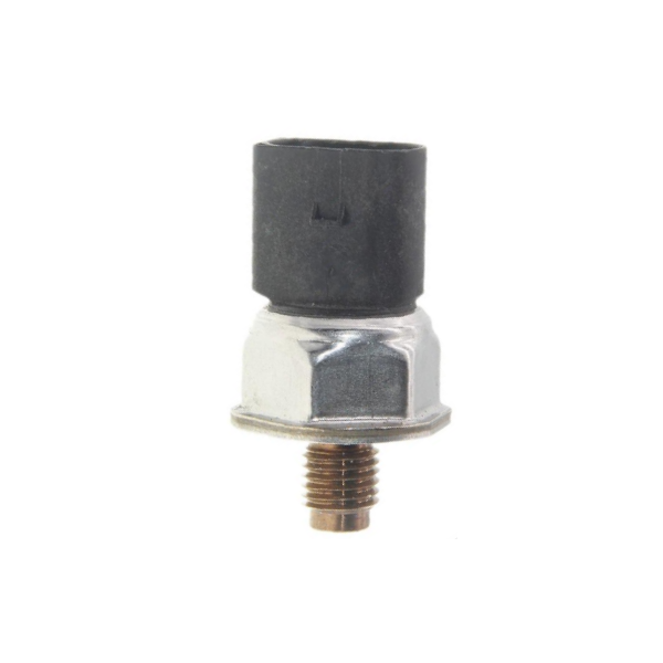
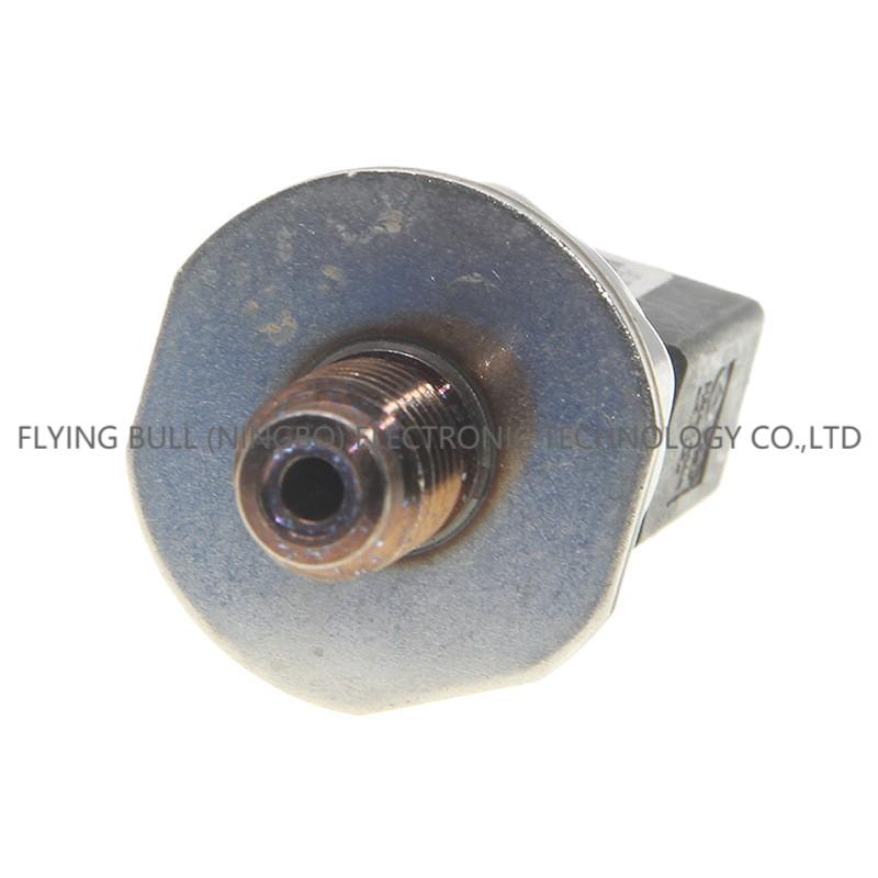
Applicable to Ford fuel pressure sensor 55PP22-01 9307Z521A

Product introduction
Pay attention to the following points in ECU testing:
① Turn off the ignition switch: remove the ECU plug. ② Turn on the ignition switch: use a multimeter to check the power supply of ECU. The voltage between pins 2 and 3 of the ECU plug and the voltage between pins 1 and 2 should not be less than 11V, otherwise, check the circuit.
2) Detection of coolant temperature sensor ① Wiring inspection: Turn off the ignition switch and remove the 4-hole plug of coolant temperature sensor, as shown in Figure 2-36. Check whether there is an open circuit in the wire between the 3rd hole of the 4-hole plug of the coolant temperature sensor and the 53rd hole of the ECU socket (the resistance of the wire should not be greater than 1.5Ω), and whether the wire is short-circuited to the positive pole of the power supply (the resistance should be infinite). Check whether there is an open circuit in the lead between the first hole of the 4-hole plug of the coolant temperature sensor and the 67th hole of the ECU socket (the lead resistance should not be greater than 1.5Ω). ② Performance inspection: Turn off the ignition switch, remove the coolant temperature sensor, put the coolant temperature sensor into a water cup, and use a multimeter to detect the resistance between the pins 1 and 3 of the coolant temperature sensor. The corresponding values of water temperature and resistance should meet the values shown in Table 2-19. Table 2-19 Corresponding Table of Temperature and Resistance of Coolant Temperature Sensor
3) Pay attention to the following points when detecting the crankshaft position sensor (engine speed sensor): ① Turn off the ignition switch: remove the white 3-hole plug of the crankshaft position sensor (engine speed sensor). ② Check the resistance between plugs: As shown in Figure 2-37, the resistance between holes 1 and 3 (ground) and between holes 2 and 3 (ground) should be infinite. Check the resistance between pin 1 and pin 2 of the sensor, which should be 450 ~ 1000 Ω. The working principle of extended data mostly outputs pulse signal (approximate sine wave or rectangular wave). The methods for measuring the rotational speed of pulse signal include: frequency integration method (that is, F/V conversion method, whose direct result is voltage or current) and frequency operation method (whose direct result is digital).
In automation technology, there are many measurements of rotational speed, and the linear speed is often indirectly measured by rotational speed. The DC tachogenerator can convert the rotational speed into an electrical signal. The tachometer requires a linear relationship between the output voltage and the rotational speed, and requires the output voltage to be steep and the time and temperature stability to be good. The tachometer can be generally divided into two types: DC type and AC type. The rotary speed sensor is in direct contact with the moving object. When a moving object is in contact with the rotary speed sensor, the friction drives the roller of the sensor to rotate. The rotating pulse sensor mounted on the roller sends out a series of pulses. Each pulse represents a certain distance value, so that the linear velocity can be measured. Electromagnetic induction type, a gear is installed on the rotating shaft, and the outer side is an electromagnetic coil. The rotation is due to the gap between the teeth of the gear, and the square wave changing voltage is obtained, and then the rotation speed is calculated. The rotary speed sensor has no direct contact with the moving object, and a reflective film is attached to the blade edge of the impeller. When the fluid flows, it drives the impeller to rotate, and the optical fiber transmits light reflection once every rotation of the impeller to generate an electric pulse signal. The speed can be calculated from the number of pulses detected.
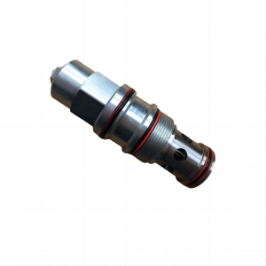
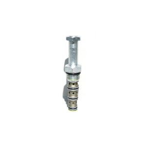
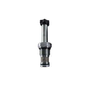
Product picture
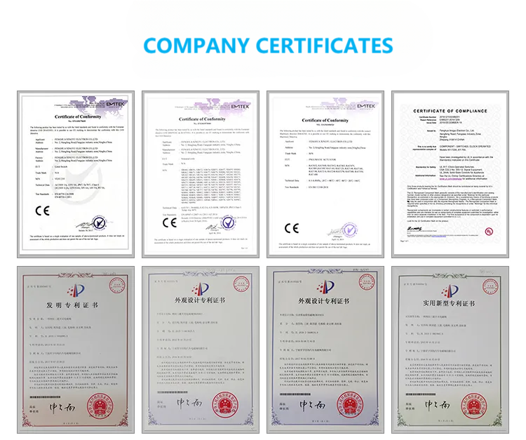
Company details


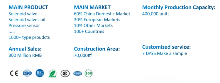

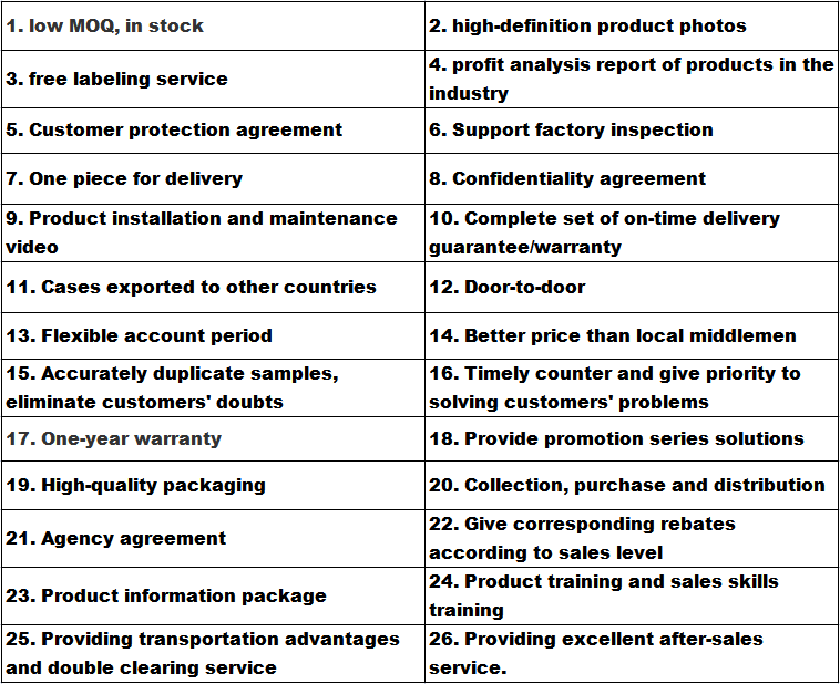
Company advantage
Transportation

FAQ

Related products